Table of Contents
Advertisement
Quick Links
Advertisement
Table of Contents

Related Manuals for S&T Kontron CP3005 Series


Summary of Contents for S&T Kontron CP3005 Series
- Page 1 USER GUIDE CP3005 User Guide Rev. 1.8 Doc. ID: 1064-4245 www.kontron.com // 1...
- Page 2 CP3005 – User Guide Rev. 1.8 This page has been intentionally left blank www.kontron.com // 2...
- Page 3 CP3005 – User Guide Rev. 1.8 CP3005 – USER GUIDE Disclaimer Kontron would like to point out that the information contained in this user guide may be subject to alteration, particularly as a result of the constant upgrading of Kontron products. This document does not entail any guarantee on the part of Kontron with respect to technical processes described in the user guide or any product characteristics set out in the user guide.
- Page 4 CP3005 – User Guide Rev. 1.8 Intended Use THIS DEVICE AND ASSOCIATED SOFTWARE ARE NOT DESIGNED, MANUFACTURED OR INTENDED FOR USE OR RESALE FOR THE OPERATION OF NUCLEAR FACILITIES, THE NAVIGATION, CONTROL OR COMMUNICATION SYSTEMS FOR AIRCRAFT OR OTHER TRANSPORTATION, AIR TRAFFIC CONTROL, LIFE SUPPORT OR LIFE SUSTAINING APPLICATIONS, WEAPONS SYSTEMS, OR ANY OTHER APPLICATION IN A HAZARDOUS ENVIRONMENT, OR REQUIRING FAIL-SAFE PERFORMANCE, OR IN WHICH THE FAILURE OF PRODUCTS COULD LEAD DIRECTLY TO DEATH, PERSONAL INJURY, OR SEVERE PHYSICAL OR...
- Page 5 CP3005 – User Guide Rev. 1.8 Revision History Revision Brief Description of Changes Date of Issue Author Initial Issue 2020-Mar-24 memory and temperature modifications 2020-Apr-14 added temperature diagrams 2020-May-07 Power consumption, new drawings in chapter 2020-June-23 12.3 BIOS and UEFI chapter changed 2020-July-09 Register CTRL1 in chapter 4.3.4and SATA 2020-July-20...
- Page 6 CP3005 – User Guide Rev. 1.8 Customer Service As a trusted technology innovator and global solutions provider, Kontron extends its embedded market strengths into a services portfolio allowing companies to break the barriers of traditional product lifecycles. Proven product expertise coupled with collaborative and highly-experienced support enables Kontron to provide exceptional peace of mind to build and maintain successful products.
-
Page 7: Symbols
CP3005 – User Guide Rev. 1.8 Symbols The following symbols may be used in this user guide DANGER indicates a hazardous situation which, if not avoided, will result in death or serious injury. WARNING indicates a hazardous situation which, if not avoided, could result in death or serious injury. -
Page 8: For Your Safety
CP3005 – User Guide Rev. 1.8 For Your Safety Your new Kontron product was developed and tested carefully to provide all features necessary to ensure its compliance with electrical safety requirements. It was also designed for a long fault-free life. However, the life expectancy of your product can be drastically reduced by improper treatment during unpacking and installation. -
Page 9: Lithium Battery Precautions
CP3005 – User Guide Rev. 1.8 Lithium Battery Precautions If your product is equipped with a lithium battery, take the following precautions when replacing the battery. Danger of explosion if the battery is replaced incorrectly. Replace only with same or equivalent battery type recommended by the manufacturer. -
Page 10: Table Of Contents
CP3005 – User Guide Rev. 1.8 Table of Contents Symbols............................................7 For Your Safety ......................................... 8 High Voltage Safety Instructions ..................................8 Special Handling and Unpacking Instruction ..............................8 Lithium Battery Precautions ....................................9 General Instructions on Usage .................................... 9 Quality and Environmental Management ............................... - Page 11 CP3005 – User Guide Rev. 1.8 3.9.3.1. System Status LEDs ....................................38 3.9.3.2. General Purpose LEDs ..................................39 3.9.4. USB Interfaces ......................................40 3.9.5. VGA Interface ....................................... 40 3.9.6. Serial Ports ........................................40 3.9.7. Gigabit Ethernet ......................................40 3.9.8. SATA Interfaces ......................................41 3.9.9.
- Page 12 CP3005 – User Guide Rev. 1.8 7.6.1. DisplayPort Interfaces ....................................67 7.6.2. Gigabit Ethernet Interface ..................................67 7.6.3. USB Interface ....................................... 67 7.6.4. Serial Port (J8)......................................67 7.6.5. M.2 Interface (J3) ....................................... 68 7.6.6. SATA Interface (J6) ....................................68 MMEXT-XMC02 Extension Module ..............................69 8.1.
-
Page 13: List Of Tables
CP3005 – User Guide Rev. 1.8 13.2.1. Main Setup Menu ...................................... 96 13.2.2. Advanced Setup Menu ................................... 97 13.2.3. Chipset Menu ......................................100 13.2.4. Security Setup Menu .................................... 103 13.2.5. Remember the Password ................................... 104 13.2.6. Boot Setup Menu ....................................105 13.2.7. -
Page 14: List Of Figures
CP3005 – User Guide Rev. 1.8 Table 20: Status Register 1 (STAT1) ................................44 Table 21: Control Register 0 (CTRL0) ................................45 Table 22: Control Register 1 (CTRL1) ................................45 Table 23: Device Protection Register (DPROT) ............................46 Table 24: Reset Status Register (RSTAT) ..............................47 Table 25: Board Interrupt Configuration Register (BICFG) ........................ - Page 15 CP3005 – User Guide Rev. 1.8 Figure 9: Ambient Temperature for Xeon® E-2176M Processor, measured by Intel PTU Tool Coffee Lake H 1.4 ... 60 Figure 10: Ambient Temperature for i3-9100HL Processor, measured by Intel PTU Tool Coffee Lake H 1.7 ...... 61 Figure 11: Ambient Temperature for Xeon®...
-
Page 16: 1/ Introduction
CP3005 – User Guide Rev. 1.8 1/ Introduction The CP3005 is a highly integrated 3U CompactPCI® processor board series based on the 8thand 9th generation Intel® Core and Xeon® processors in combination with the appropriate Chipset. CP3005-SA "standard air cooled" variants are equipped with four or six core processors and offer extraordinary performance-per-watt values and highest graphics performance. -
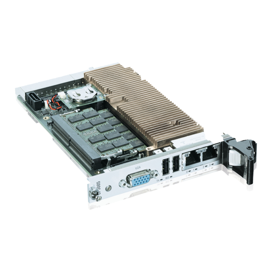
Page 17: Figure 1: Compactpci-Board Cp3005
CP3005 – User Guide Rev. 1.8 Figure 1: CompactPCI-Board CP3005 www.kontron.com // 17... -
Page 18: 2/ System Expansion Capabilities
CP3005 – User Guide Rev. 1.8 2/ System Expansion Capabilities 2.1. MMEXT05 Module 8 Horizontal Pitches (HP) The MMEXT05 module for the 8HP CP3005 version provides various I/O ports. On the front panel, it includes two DisplayPort connectors, one Gigabit Ethernet port, one USB 3.0 port, and one RS-232 COM port. Onboard ports include one SATA connector for SATA 2.5”... -
Page 19: Block Diagram
CP3005 – User Guide Rev. 1.8 2.3. Block Diagram The following diagram provides additional information concerning board functionality and component layout. Figure 2: Block Diagram www.kontron.com // 19... -
Page 20: Front Panel
CP3005 – User Guide Rev. 1.8 2.4. Front Panel Figure 3: 4HP CP3005 Front Panel with LED Status System Status LEDs TH (red/green): Temperature Status WD (green): Watchdog Status General Purpose LEDs LED3..0 (red/green/red+green): General Purpose / POST Code Note: If the General Purpose LEDs 3..0 are lit red during boot-up, a failure is indicated before the uEFI BIOS has started. -
Page 21: Board Layout
CP3005 – User Guide Rev. 1.8 2.5. Board Layout Figure 4: 4HP CP3005 Board Layout (Top View) without heatspreader M.2 Connector Intel Intel Core/Xeon Number Item Number Item Processor M.2 Card SO-DIMM Sockets SATA Connector CPCI Connector Battery www.kontron.com // 21... -
Page 22: Figure 5: 4Hp Cp3005 Board Layout (Bottom View)
CP3005 – User Guide Rev. 1.8 Figure 5: 4HP CP3005 Board Layout (Bottom View) Number Item DIP Switch SW1 www.kontron.com // 22 M.2 Connector... -
Page 23: Technical Specification
CP3005 – User Guide Rev. 1.8 2.6. Technical Specification Table 1: CP3005 Main Specifications Features Specifications Form factor 3U, 4HP CompactPCI (100 mm x 160 mm) 8HP with mezzanine Processor CPU & Graphics The CP3005 supports the following processors: Controller Xeon®... - Page 24 CP3005 – User Guide Rev. 1.8 Features Specifications Two type A USB 2.0 connectors on the front panel, two USB 2.0 ports on the rear I/O module CP-RIO3-04 One combined USB2.0/USB3.0 port on the MMEXT05 module Serial Two 16C550-compatible UARTs are available only with the rear I/O module CP-RIO3-04 CP3005 8HP: One COM port to front I/O (with extension module MMEXT05) and one to rear I/O, or both COM ports...
-
Page 25: Standards
CP3005 – User Guide Rev. 1.8 Features Specifications Watchdog Timer Software-configurable, two-stage Watchdog with programmable timeout settings. The timeout values range from 125 ms to 4096 s. The Watchdog serves for generating an IRQ and/or a hardware reset. System Timer The processor contains three 8254-style counters with fixed uses. - Page 26 CP3005 – User Guide Rev. 1.8 Type Aspect Standard Remarks Vibration (Sinusoidal) IEC60068-2-6 Test parameters: 10-300 (Hz) frequency range 5 (g) acceleration 1 (oct/min) sweep rate 10 cycles/axis 3 axes Single Shock IEC60068-2-27 Test parameters: 30 (g) acceleration 9 (ms) shock duration half sine 3 number of shocks per direction (total: 18) 6 directions...
-
Page 27: 3/ Functional Description
CP3005 – User Guide Rev. 1.8 3/ Functional Description 3.1. Processor The CP3005 supports the Intel® Core and the Intel® Xeon® processors in combination with the mobile Intel® CM246 Express Chipset. Table 3: Features of the Processors Supported on the CP3005 Frequency Processor Cores/Threads... -
Page 28: Chipset
CP3005 – User Guide Rev. 1.8 3.3. Chipset The CP3005 is a two-chip solution implementing the CPU with CM246 Platform Controller Hub. The following table lists the PCH CM246 features. Table 5: CM246 Features Feature CM246 USB Configuration 10x total USB 3.1 ports: - up to 6 USB 3.1 Gen 2 Ports - up to 10 USB 3.1 Gen 1 Ports 14 USB 2.0 Ports... -
Page 29: Battery
CP3005 – User Guide Rev. 1.8 3.6. Battery The CP3005 is provided with an UL-recognized BR2032, 3.0 V, “coin cell” lithium battery for the RTC. When a battery is installed, refer to the operational specifications of the battery as this determines the operating and storage temperature of the CP3005. -
Page 30: Board Interfaces
CP3005 – User Guide Rev. 1.8 3.9. Board Interfaces 3.9.1. CompactPCI Interface The CP3005 supports a flexible CompactPCI interface with a hot plug power interface (no PCI hot swap). In the system slot the PCI interface is in transparent mode, and in the peripheral slot the CompactPCI interface is isolated so that it cannot communicate with the CompactPCI bus. -
Page 31: Board Insertion/Replacement Under Power
CP3005 – User Guide Rev. 1.8 3.9.1.4. Board Insertion/Replacement under Power The following features are implemented on the CP3005: Power ramping ENUM signal handling (hot swapping of peripheral boards) Power ramping on the CP3005 provides the hot plug functionality on the power interface. The PCI interface does not support hot swap functionality. -
Page 32: Compactpci Connectors J1 And J2
CP3005 – User Guide Rev. 1.8 3.9.2. CompactPCI Connectors J1 and J2 The CP3005 provides two CompactPCI connectors, J1 and J2, with the following functionality: J1: 32-bit CompactPCI interface with PCI bus signals, arbitration, clock and power J2: arbitration, clock and optionally rear I/O interface functionality The CP3005 is designed for a CompactPCI bus architecture and the board is capable of driving up to seven CompactPCI slots with individual arbitration and clock signals. -
Page 33: Compactpci Connector Keying
CP3005 – User Guide Rev. 1.8 3.9.2.1. CompactPCI Connector Keying CompactPCI backplane connectors support guide lugs to ensure a correct polarized mating (3.3 V or 5 V V(I/O) coding). The CP3005 supports universal (3.3 V and 5 V) PCI V(I/O) signaling voltages with one common termination resistor configuration. -
Page 34: Table 8: Compactpci Connector J1 Peripheral Slot Pinout
CP3005 – User Guide Rev. 1.8 The legacy IDE interrupts INTP (CompactPCI specification pin D4) and INTS (CompactPCI specification pin E4) are not implemented on the CP3005. Therefore, pins D4 and E4 are reserved. The IPMB system management bus (CompactPCI specification pins A4, B17, C17) is not implemented on the CP3005. Therefore, pin A4 is not connected and pins B17 and C17 are reserved. -
Page 35: Optional Rear I/O Interface
CP3005 – User Guide Rev. 1.8 Table 9: CompactPCI Connector J2 Pinout (CP3005 Front I/O Vers.) CLK6 CLK5 PRST# REQ6# GNT6# DEG# FAL# REQ5# GNT5# V(I/O) CLK4 GNT3# REQ4# GNT4# CLK2 CLK3 SYSEN# GNT2# REQ3# CLK1 REQ1# GNT1# REQ2# The 64-bit CompactPCI signals are not used on the board and the 64-bit control and address signals are not terminated to V(I/O). -
Page 36: Table 10: Rear I/O Compactpci Connector J2 Pinout (Cp3005 Rear I/O Vers.)
CP3005 – User Guide Rev. 1.8 The CP3005 rear I/O provides the following interfaces (all signals are available on J2 only if the board is ordered with rear I/O functionality): Two USB 2.0 ports Two Gigabit Ethernet ports without LED signals ... -
Page 37: Table 11: Compactpci Rear I/O Connector J2 Signals
CP3005 – User Guide Rev. 1.8 GPI2/ VGA_DDC_D COMB_DSR# SATAARX+ VGA_GREEN SATABRX+ SATAARX- VGA_VSYNC SATABRX- V(I/O) RIO_5V VGA_DDC_CL GPIO_CFG CLK4 GNT3# REQ4# GNT4# CLK2 CLK3 SYSEN# GNT2# REQ3# CLK1 REQ1# GNT1# REQ2# The RIO_XXX signals are power supply OUTPUTS to supply the rear I/O module with power. These pins MUST NOT be connected to any other power source, either within the backplane itself or within a rear I/O module. -
Page 38: Front Panel Leds
CP3005 – User Guide Rev. 1.8 Table 12: GPIO Signal Description Signal Description GPIO_CFG0 0 = GPIO 1 = COMB The default value is 1 if pin D4 is not connected on the rear I/ module (pull-up resistor to 3.3 V on CP3005). 3.9.3. -
Page 39: General Purpose Leds
CP3005 – User Guide Rev. 1.8 3.9.3.2. General Purpose LEDs The General Purpose LEDs (LED3..0) are designed to indicate the boot-up POST code after which they are available to the application. If the LED3..0 are lit red during boot-up, a failure is indicated. In this event, please contact Kontron for further assistance. -
Page 40: Usb Interfaces
CP3005 – User Guide Rev. 1.8 LED3 LED2 LED1 LED0 Result Low Nibble off (0) off (0) off (0) on (1) Post Code 0x41 Under normal operating conditions, the General Purpose LEDs should not remain lit during boot-up. They are intended to be used only for debugging purposes. In the event that a General Purpose LED lights up during boot-up and the CP3005 does not boot, please contact Kontron for further assistance. -
Page 41: Sata Interfaces
CP3005 – User Guide Rev. 1.8 3.9.8. SATA Interfaces The CP3005 provides six SATA ports: One SATA 6 Gb/s port on the onboard standard, 7-pin SATA connector, J3, for connection to SATA devices via cable, One SATA 6 Gb/s port on the onboard M.2 Card connector for connection a SATA SSD device. ... -
Page 42: 4/ Configuration
CP3005 – User Guide Rev. 1.8 4/ Configuration 4.1. DIP Switch Configuration The quad DIP switch SW1 provides the following switches for board configuration: POST code indication, SPI boot flash selection, and uEFI BIOS configuration. Figure 7: DIP Switch SW1 Table 17: DIP Switch SW1 Functionality Switch Setting... -
Page 43: Cp3005-Specific Registers
CP3005 – User Guide Rev. 1.8 4.3. CP3005-Specific Registers Table 18: CP3005-Specific Registers Address Device 0x280 Status Register 0 (STAT0) 0x281 Status Register 1 (STAT1) 0x282 Control Register 0 (CTRL0) 0x283 Control Register 1 (CTRL1) 0x284 Device Protection Register (DPROT) 0x285 Reset Status Register (RSTAT) 0x286... -
Page 44: Status Register 1 (Stat1)
CP3005 – User Guide Rev. 1.8 Bitfield Description DIP3 DIP switch SW1, switch 3 (reset configuration): 0 = Switch on (reset does a power cycle) 1 = Switch off (standard reset configuration) DIP2 DIP switch SW1, switch 2 (select SPI flash): 0 = Switch on (boot from recovery SPI boot flash) 1 = Switch off (boot from standard SPI boot flash) DIP1... -
Page 45: Control Register 0 (Ctrl0)
CP3005 – User Guide Rev. 1.8 4.3.3. Control Register 0 (CTRL0) The Control Register 0 holds a series of bits defining general/common configuration functions. Table 21: Control Register 0 (CTRL0) Address 0x282 Name BFUS VGAM Reserved Access 00000 Reset Bitfield Description 7 - 6 VGAM... -
Page 46: Device Protection Register (Dprot)
CP3005 – User Guide Rev. 1.8 Bitfield Description 1 = TPM enabled CRST CPCI reset input when the CP3005 is in a peripheral slot: 0 = Disable CPCI reset to board 1 = Enable CPCI reset to board SCOMA COMA routing selection: 0 = Rear I/O 1 = Extension module The reset value of the SCOMA bit depends on the board version ordered. -
Page 47: Reset Status Register (Rstat)
CP3005 – User Guide Rev. 1.8 4.3.6. Reset Status Register (RSTAT) The Reset Status Register is used to determine the host’s reset source. Table 24: Reset Status Register (RSTAT) Address 0x285 Name PORS FPRS CPRS WTRS Reserved Access 0000 Reset Bitfield Description PORS... -
Page 48: Board Interrupt Configuration Register (Bicfg)
CP3005 – User Guide Rev. 1.8 4.3.7. Board Interrupt Configuration Register (BICFG) The Board Interrupt Configuration Register holds a series of bits defining the interrupt routing. Table 25: Board Interrupt Configuration Register (BICFG) Address 0x286 Name UICF CFICF CEICF CDICF Reserved WICF Access... -
Page 49: Board Id High-Byte Register (Bidh)
CP3005 – User Guide Rev. 1.8 Bitfield Description 11 = COMA, COMB 3 - 0 MEZC Mezzanine configuration: 0000 = None/Smart Extension Module 0001 = MMEXT-XMC02 extension module 0010 = MMEXT05 extension module 0011...FFFF = Reserved *The default value depends on the CP3005 version ordered (front I/O or rear I/O) and the rear I/O module used. 4.3.9. -
Page 50: Geographic Addressing Register (Geoad)
CP3005 – User Guide Rev. 1.8 4.3.11. Geographic Addressing Register (GEOAD) The Geographic Addressing Register holds the CompactPCI geographic address (backplane-unique physical slot number). Table 29: Geographic Addressing Register (GEOAD) Address 0x28A Name Reserved Access Reset Bitfield Description 7 - 5 Reserved 4 - 0 Geographic Address... - Page 51 CP3005 – User Guide Rev. 1.8 Bitfield Description 0001 = 0.25 s 1001 = 64 s 0010 = 0.5 s 1010 = 128 s 0011 = 1 s 1011 = 256 s 0100 = 2 s 1100 = 512 s 0101 = 4 s 1101 = 1024 s 0110 = 8 s...
-
Page 52: Board Id Low-Byte Register (Bidl)
CP3005 – User Guide Rev. 1.8 4.3.13. Board ID Low-Byte Register (BIDL) Table 31: Board ID Low-Byte Register (BIDL) Address 0x28D Name BIDL Access 0x80 Reset Bitfield Description 7 - 0 BIDL Board identification: CP3005: 0xB480 The Board ID High Byte Register is located at the address 0x288. 4.3.14. -
Page 53: Led Control Register (Lctrl)
CP3005 – User Guide Rev. 1.8 4.3.15. LED Control Register (LCTRL) The LED Control Register enables the user to switch on and off the front panel General Purpose LEDs. Table 33: LED Control Register (LCTRL) Address 0x291 Name LCMD LCOL Access Reset 0000... -
Page 54: General Purpose Input Register (Gpin)
CP3005 – User Guide Rev. 1.8 4.3.17. General Purpose Input Register (GPIN) The General Purpose Input Register holds the general purpose input signals of the rear I/O CompactPCI connector J2. This register can only be used if the CP3005 is ordered as a rear I/O version and the rear I/O GPIO operation is configured through the dedicated rear transition module configuration signal on the CompactPCI connector J2. -
Page 55: 5/ Power Considerations
CP3005 – User Guide Rev. 1.8 5/ Power Considerations 5.1. CP3005 Voltage Ranges The CP3005 has been designed for optimal power input and distribution. Still it is necessary to observe certain criteria essential for application stability and reliability. The system power supply must comply with the CompactPCI® specification. The following table specifies the ranges for the input power voltage within which the board is functional. -
Page 56: Power Consumption
CP3005 – User Guide Rev. 1.8 If the main power input is switched off, the supply voltages will not go to 0V instantly. It will take a couple of seconds until the capacitors are discharged. If the voltage rises again before it has gone below a certain level, the circuits may enter a latch-up state where even a hard RESET will not help any more. -
Page 57: Table 37: Workload Uefi Shell
CP3005 – User Guide Rev. 1.8 As the Celeron® G4930 processor does not support Hyper-Threading or Turbo, it is rare to reach the full theoretical maximum Thermal Design Power (TDP) of 35 W. Table 37: Workload uEFI Shell Nominal Xeon® E-2176M Core™... -
Page 58: Battery-Free Operation
CP3005 – User Guide Rev. 1.8 5.6. Battery-free Operation The CP3005 features the ability to operate with or without an installed RTC battery. After power is removed from the CompactPCI system containing a CP3005 without battery, the CP3005’s internal RC circuits must discharge prior to reapplying the power. -
Page 59: 6/ Thermal Considerations
CP3005 – User Guide Rev. 1.8 6/ Thermal Considerations The thermal characteristic graphs shown in the following sections are intended to serve as guidance for reconciling the required computing power with the necessary system volumetric airflow over the ambient temperature. The graphs contain two curves representing upper level working points based on different levels of average CPU utilization. -
Page 60: Figure 8: Ambient Temperature For Core I5-8400H Processor, Measured By Intel Ptu Tool Coffee Lake H 1.4
CP3005 – User Guide Rev. 1.8 Figure 8: Ambient Temperature for Core i5-8400H Processor, measured by Intel PTU Tool Coffee Lake H 1.4 Package power is measured on a Windows 10 system with Workload all cores 70%, Gfx- Workload idle or high and turbo off. Figure 9: Ambient Temperature for Xeon®... -
Page 61: Figure 10: Ambient Temperature For I3-9100Hl Processor, Measured By Intel Ptu Tool Coffee Lake H 1.7
CP3005 – User Guide Rev. 1.8 Figure 10: Ambient Temperature for i3-9100HL Processor, measured by Intel PTU Tool Coffee Lake H 1.7 Package power is measured on a Windows 10 system with Workload all cores 70%, Gfx- Workload idle or high and turbo off. Figure 11: Ambient Temperature for Xeon®... -
Page 62: 7/ Mmext05 Extension Module
CP3005 – User Guide Rev. 1.8 7/ MMEXT05 Extension Module 7.1. Overview The MMEXT05 is a factory-installed mezzanine extension module which along with an 8HP front panel provides additional interfaces, such as: Two DisplayPorts One Gigabit Ethernet port ... -
Page 63: Technical Specifications
CP3005 – User Guide Rev. 1.8 7.2. Technical Specifications Table 42: MMEXT05 Module Specifications Features Specifications DisplayPort Two 20-pin DisplayPort connectors, J1 and J2, for connecting two monitors equipped with a DisplayPort interface (DVI/HDMI- capable through passive cable adapter) Gigabit Ethernet One 10 Base-T/100 Base-TX/1000 Base-T Ethernet interface based on the Intel®... -
Page 64: Mmext05 Module Functional Block Diagram
CP3005 – User Guide Rev. 1.8 7.3. MMEXT05 Module Functional Block Diagram Figure 12: MMEXT05 Module Functional Block Diagram www.kontron.com // 64... -
Page 65: Front Panel Of The Cp3005 With Mmext05 Module
CP3005 – User Guide Rev. 1.8 7.4. Front Panel of the CP3005 with MMEXT05 Module Figure 13: Front Panel of the 8HP CP3005 with MMEXT05 Module Table 43: Watchdog (WD) and Overtemperature (TH) Status LEDs Status WD (green): Watchdog Status TH (red/green): Overtemperature Status Table 44: Integral Ethernet LEDs... -
Page 66: Mmext05 Module Layout
CP3005 – User Guide Rev. 1.8 7.5. MMEXT05 Module Layout Figure 14: MMEXT05 Module Layout for 8HP Board Version (Top View) Battery M.2 SATA 2.5" SATA HDD www.kontron.com // 66... -
Page 67: Module Interfaces
CP3005 – User Guide Rev. 1.8 7.6. Module Interfaces 7.6.1. DisplayPort Interfaces The MMEXT05 provides two standard DisplayPort/DP++ interfaces for connection to two monitors. The interfaces are implemented as standard DisplayPort/DP++ connectors, J1 und J2, on the front panel. 7.6.2. Gigabit Ethernet Interface The MMEXT05 extension module includes one 10Base-T/100Base-TX/1000Base-T Ethernet port based on one Intel®... -
Page 68: Interface (J3)
CP3005 – User Guide Rev. 1.8 7.6.5. M.2 Interface (J3) To enable flexible flash expansion, a standard M.2 card socket is available on the MMEXT05. The socket is keyed in the M position. There is one position for the mounting screw, accepting 2280 sizes of M.2 modules. Figure 16: M.2 Connector 7.6.6. -
Page 69: 8/ Mmext-Xmc02 Extension Module
CP3005 – User Guide Rev. 1.8 8/ MMEXT-XMC02 Extension Module 8.1. Overview The MMEXT-XMC02 is a factory-installed mezzanine extension module which along with an 8HP front panel provides additional interfaces, such as: One onboard XMC connector for connecting one x8, x4, or x1 PCI Express 2.0 XMC module over Highspeed Extension ... -
Page 70: Mmext-Xmc02 Module Functional Block Diagram
CP3005 – User Guide Rev. 1.8 8.3. MMEXT-XMC02 Module Functional Block Diagram Figure 18: MMEXT-XMC02 Module Functional Block Diagram www.kontron.com // 70... -
Page 71: Front Panel Of The Cp3005 With Mmext-Xmc02 Module
CP3005 – User Guide Rev. 1.8 8.4. Front Panel of the CP3005 with MMEXT-XMC02 Module Figure 19: Front Panel of the 8HP CP3005 with MMEXT-XMC02 Module Table 48: Watchdog (WD) and Overtemperature (TH) Status LEDs Status WD (green): Watchdog Status TH (red/green): Overtemperature Status Table 49: Integral Ethernet LEDs... -
Page 72: Mmext-Xmc02 Module Layout
CP3005 – User Guide Rev. 1.8 8.5. MMEXT-XMC02 Module Layout Figure 20: MMEXT-XMC02 Module Layout for 8HP Board Version (Top View) XMC Interface M.2 Interface (J2) Figure 21: MMEXT-XMC02 Module Layout for 8HP Board Version (Bottom View) Board to Board Interface www.kontron.com // 72... -
Page 73: Module Interfaces
CP3005 – User Guide Rev. 1.8 8.6. Module Interfaces 8.6.1. M.2 Interface (J2) To enable flexible flash expansion, a standard M.2 card socket is available on the CP3005. The socket is keyed in the M position. There is one position for the mounting screw, accepting 2280 sizes of M.2 modules. Figure 22: M.2 Connector 8.6.2. -
Page 74: 9/ Cp-Rio3-04 4Hp And Cp-Rio3-04 8Hp Rear Transition Modules
CP3005 – User Guide Rev. 1.8 9/ CP-RIO3-04 4HP and CP-RIO3-04 8HP Rear Transition Modules 9.1. Overview The CP3005 provides optional rear I/O connectivity for peripherals. Some standard PC interfaces are implemented and assigned to the front panel and to the rear I/O connector J2 on the CP3005. When the CP-RIO3-04 rear transition module is used, some signals of main board/front panel connectors are routed to the module interface. -
Page 75: Front Panels
CP3005 – User Guide Rev. 1.8 Features Specifications Dimensions 100 mm x 80 mm Board Weight 4HP: 120 grams 8HP: 150 grams 9.3. Front Panels Figure 24: CP-RIO3-04 4HP and 8HP Front Panels www.kontron.com // 75... -
Page 76: Cp-Rio3-04 Rear Transition Module Layout
CP3005 – User Guide Rev. 1.8 9.4. CP-RIO3-04 Rear Transition Module Layout Figure 25: CP-RIO3-04 4HP Rear Transition Module Layout www.kontron.com // 76... -
Page 77: Module Interfaces
CP3005 – User Guide Rev. 1.8 Figure 26: CP-RIO3-04 8HP Rear Transition Module Layout 9.5. Module Interfaces 9.5.1. USB Interfaces The CP-RIO3-04 rear transition module provides two standard, type A, USB 2.0 connectors, J11 and J12, on the front panel. 9.5.2. -
Page 78: Peripheral Control Interface
CP3005 – User Guide Rev. 1.8 Table 52: Serial Port Connectors J2 (COMB) and J3 (COMA) Pinout Signal Description Data carrier detect Data set ready Receive data Request to send Transmit data Clear to send Data terminal ready Ring indicator Signal ground Not connected 9.5.5. -
Page 79: Rear I/O Interface On Compactpci Connector Rj2
CP3005 – User Guide Rev. 1.8 9.5.7. Rear I/O Interface on CompactPCI Connector rJ2 The CP-RIO3-04 rear transition module conducts a wide range of I/O signals through the rear I/O connector rJ2. To support the rear I/O feature, a 3U CompactPCI backplane with rear I/O support is required. -
Page 80: Table 55: Rear I/O Signal Description
CP3005 – User Guide Rev. 1.8 IPA_DB+/bi IPA_DB-/bi COMB_RI#/o IPA_DD+/ IPA_DD-/bi IPB_DA+/bi IPB_DA-/bi RIO_XFO_CT IPB_DC+/ IPB_DC-/bi IPB_DB+/bi IPB_DB-/bi COMB_DCD# IPB_DD+/ IPB_DD-/bi /out COMB_TXD/in VGA_RED/in COMB_D TR#/in SATAATX+/in VGA_HSYNC/ SATABTX+/i SATAATX-/in VGA_BLUE/i SATABTX-/in COMB_DSR#/ VGA_DDC_D ATA/bi SATAARX+/out VGA_GREEN/ SATABRX+/o SATAARX-/out VGA_VSYNC/ SATABRX- /out RIO_5V/in... -
Page 81: 10/ Cp-Rio3-04S Rear Transition Module
CP3005 – User Guide Rev. 1.8 CP-RIO3-04S Rear Transition Module 10.1. Overview The rear variant CP3005 provides optional rear I/O connectivity for peripherals. Some standard PC interfaces are implemented and assigned to the front panel and to the rear I/O connector J2 on the CP3005. When the CP-RIO3-04 rear transition module is used, some signals of main board/front panel connectors are routed to the module interface. -
Page 82: 11/ Sata Ssd Flash Module
CP3005 – User Guide Rev. 1.8 11/ SATA SSD Flash Module The CP3005 base board as well as the 8HP extensions MMEXT05 and MMEXT-XMC02 are equipped with M.2 connectors to carry SATA SSD flash modules. Specification: Size: 22x42 mm (base board), 22x80 mm (on MMEXT05 and MMEXT-XMC02) ... -
Page 83: 12/ Installation
CP3005 – User Guide Rev. 1.8 Installation This chapter is oriented towards an application environment. Some aspects may, however, be applicable to a development environment. 12.1. Safety To ensure personnel safety and correct operation of this product, the following safety precautions must be observed: All operations involving the CP3005 require that personnel be familiar with system equipment, safety requirements and the CP3005. -
Page 84: Standard Board Removal
CP3005 – User Guide Rev. 1.8 Fasten the front panel retaining screws. Connect all external interfacing cables to the board as required. 12.2.2. Standard Board Removal Prior to following the steps below, ensure that the safety requirements are met. When removing a board from the system, particular attention must be paid to the components which may be hot, such as heat sink, etc. -
Page 85: Installation Of Cp3005 Peripheral Devices
CP3005 – User Guide Rev. 1.8 12.3. Installation of CP3005 Peripheral Devices The CP3005 is designed to accommodate various peripheral devices, such as USB devices, SATA devices, a M.2 card, etc. The following figures show the placement of modules and peripheral devices on the CP3005. Figure 29: 4HP CP3005 with mSATA Flash Module www.kontron.com // 85... -
Page 86: Figure 30: Hp Cp3005 With Mmext05 Module
CP3005 – User Guide Rev. 1.8 Figure 30: HP CP3005 with MMEXT05 Module Figure 31: CP3005 8HP with MMEXT-XMC02 Module www.kontron.com // 86... -
Page 87: Installation Of External Sata Devices
CP3005 – User Guide Rev. 1.8 12.3.1. Installation of External SATA Devices The following information pertains to external SATA devices which may be connected to the CP3005 via normal cabling. Some symptoms of incorrectly installed SATA devices are: Device on a SATA channel does not spin up: check power cables and cabling. May also result from a bad power supply or SATA device. -
Page 88: Xmc Module Installation
CP3005 – User Guide Rev. 1.8 Figure 30: HP CP3005 with MMEXT05 Module for the placement of the 2.5” HDD/SSD. 12.3.3. XMC Module Installation The 8HP CP3005 equipped with the MMEXT-XMC02 module provides an XMC connector, J1, for connection to an XMC module such as the Kontron XMC 401, XMC402, etc. -
Page 89: Figure 33: Screws Securing The Xmc Module To The Mmext-Xmc02 Extension Module
CP3005 – User Guide Rev. 1.8 Figure 33: Screws Securing the XMC Module to the MMEXT-XMC02 Extension Module Figure 34: CP3005 Board with MMEXT-XMC02 Extension Module and XMC Module www.kontron.com // 89... -
Page 90: Figure 35: Cp3005 With Front Panel, Mmext-Xmc02 Extension Module And Xmc Module
CP3005 – User Guide Rev. 1.8 Figure 35: CP3005 with Front Panel, MMEXT-XMC02 Extension Module and XMC Module Ensure that no power is applied to the CP3005 and disconnect any interfacing cables that may be connected to the board before proceeding. Even though power may be removed from the system, the CP3005 front panel cables and, when installed, the RIO transition module front panel cables may have power applied which comes from an external source. -
Page 91: Sata M.2 Card Installation
CP3005 – User Guide Rev. 1.8 Align the board-to-board connectors, J5 and J6, on the MMEXT-XMC02 with the board-to-board connectors, J8 and J14, on the CP3005 and gently press down. Secure the MMEXT-XMC02 equipped with the XMC module to the CP3005 by inserting the screws (g), (h), (i) and (j) removed in step 3 into the respective mounting holes and tightening them. -
Page 92: Figure 36: Battery Module (1) With Washer (2)
CP3005 – User Guide Rev. 1.8 Figure 36: Battery Module (1) with washer (2) Figure 37: Battery Module with two screws (3) and two washers (2) Be aware, that the two washers of the battery module are after the mounting procedure at the same place. -
Page 93: Removing A M.2 Card
CP3005 – User Guide Rev. 1.8 12.3.4.2. Removing a M.2 Card To remove a M.2 card: Power off the board, and then detach the power cord from the power supply. Remove the CP card. Remove the screw and washer securing the M.2 card and M.2 holder. The M.2 card pops up. -
Page 94: Rear I/O Device Installation
CP3005 – User Guide Rev. 1.8 Figure 39: Installing a M.2 Card 12.3.5. Rear I/O Device Installation The CP-RIO3-04 4HP/8HP and CP-RIO3-04S rear transition modules does not support hot swapping. Therefore, the system must have power removed to install or remove the CP-RIO3-04 4HP/8HP and CP-RIO3-04S rear transition modules. -
Page 95: 13/ Uefi Bios
CP3005 – User Guide Rev. 1.8 uEFI BIOS 13.1. Starting the uEFI BIOS The CP3005 is provided with a Kontron-customized, pre-installed and configured version of Aptio®V (referred to as uEFI BIOS in this manual), AMI’s BIOS firmware based on the Unified Extensible Firmware Interface (uEFI) specification and the Intel®... -
Page 96: Setup Menus
CP3005 – User Guide Rev. 1.8 13.2. Setup Menus The Setup utility features four menus listed in the selection bar at the top of the screen: Main Advanced Chipset Security Boot Save & Exit The Setup menus are selected via the left and right arrow keys. -
Page 97: Advanced Setup Menu
CP3005 – User Guide Rev. 1.8 Table 57: Main Setup Menu Sub-Screens and Functions Sub-Screen Function Description BIOS Information Project Version, Build Read-only field, displays information about the system Date and Time, etc. BIOS. Information about the running uEFI BIOS is reflected in the display-only function “Project Version”. - Page 98 CP3005 – User Guide Rev. 1.8 Sub-Screen Function Description CPU Configuration Active Processor All, 1, 2, 3 Cores Trusted Computing Security Device [Enabled/Disabled] Support SHA-1 PCR Bank [Enabled/Disabled] SHA-256 PCR Bank [Enabled/Disabled] Pending Operation [None] Platform Hierarchy [Enabled/Disabled] Storage Hierarchy [Enabled/Disabled] Endorsement [Enabled/Disabled]...
- Page 99 CP3005 – User Guide Rev. 1.8 Sub-Screen Function Description AMI Graphic Output Output Select [EDP1] Protocol Policy Brightness Setting BIST Enable [Enabled/Disabled] Legacy USB Support [Enabled/Disabled] XHCI Hand-off [Enabled/Disabled] USB Mass Storage [Enabled/Disabled] Driver Support USB Configuration USB transfer timeout [20 sec] Device reset time-out [20 sec]...
-
Page 100: Chipset Menu
CP3005 – User Guide Rev. 1.8 13.2.3. Chipset Menu Figure 42: Chipset Menu Table 59: Chipset Menu Functions Sub-Screen Function Description System Agent Memory Configuration Maximum Memory Frequency [Auto] (SA) Configuration Graphics Configuration Graphics Turbo IMON Current [31] SkipScanning of External Gfx Card [Enabled/Disabled] Primary Display [Auto] Select PCIE Card [Auto] External Gfx Card Primary Display Configuration... - Page 101 CP3005 – User Guide Rev. 1.8 Sub-Screen Function Description Intel Ultrabook Support IUERSlate Enable[Enabled/Disabled] IUER Dock Enable[Enabled/Disabled]] PEG Port Configuration, Enable Root Port [Auto] Port 0:1:0 Max Link Speed [Auto] PEG0 Slot Power Limit Value 75 PEG0 Slot Power Limit Scale [1.0x] PEG0 Physical Slot Number 1 PEG Port 0:1:1 Enable Root Port [Auto]...
- Page 102 CP3005 – User Guide Rev. 1.8 Sub-Screen Function Description Jitter Error Target VOC Dwell Time 10000 VOC Error Target Generate BDAT PEG Margin [Enabled/Disabled] Data PCIe Rx CEM Test Mode [Enabled/Disabled] PCI Spread Spectrum [Enabled/Disabled] Clocking PCH-IO SATA and RST SATA Controller [Enabled/Disabled] Configuration...
-
Page 103: Security Setup Menu
CP3005 – User Guide Rev. 1.8 13.2.4. Security Setup Menu The Security Setup menu provides information about the passwords and functions for specifying the security settings. The passwords are case-sensitive. The CP3005 provides no factory-set passwords. Figure 43: Security Setup Table 60: Security Setup Menu Functions Function Description... -
Page 104: Remember The Password
CP3005 – User Guide Rev. 1.8 If there is already a password installed, the system asks for this first. To clear a password, simply enter nothing and acknowledge by pressing <RETURN>. To set a password, enter it twice and acknowledge by pressing <RETURN>. Table 61: Modes of Security Setting Description... -
Page 105: Boot Setup Menu
CP3005 – User Guide Rev. 1.8 13.2.6. Boot Setup Menu The Boot Setup menu provides sub-screens and functions for boot configuration and shows the boot device priority order. Figure 44: Boot Setup Table 62: Boot Setup Menu Sub-Screens and Functions Sub-Screen Function Description... -
Page 106: Save & Exit Setup Menu
CP3005 – User Guide Rev. 1.8 13.2.7. Save & Exit Setup Menu The Save & Exit Setup menu provides functions for handling changes made to the uEFI BIOS settings and the exiting of the Setup program. The Setup will ask for confirmation prior to executing the commands. Figure 45: Save &... -
Page 107: The Uefi Shell
CP3005 – User Guide Rev. 1.8 Sub-Screen Function Description Restore Defaults Equal to F3. Restores/Loads the factory default values for all setup options. Save as User Saves all current settings as user default. The current Defaults setup state can later be restored using Restore User Defaults. -
Page 108: Kontron-Specific Uefi Shell Commands
CP3005 – User Guide Rev. 1.8 13.3.1.3. Kontron-Specific uEFI Shell Commands The Kontron uEFI implementation provides the following additional commands related to the specific HW features of the Kontron system. Table 64: Kontron-Specific uEFI Shell Commands Command Description kboardconfig Configures non-volatile board settings, such as: ... -
Page 109: Uefi Shell Scripting
CP3005 – User Guide Rev. 1.8 The uEFI Shell commands are not case-sensitive. Each uEFI Shell command is provided with a detailed online help that can be invoked by entering “<cmd> <space> <-?>” in the command line. To display the uEFI Shell command list, enter <help> or <?> in the command line. 13.4. -
Page 110: Handling The Startup Script In The Spi Boot Flash
CP3005 – User Guide Rev. 1.8 kwdt -t 15 echo “Watchdog enabled” endif if %pxe_first% == “on” then echo “forced booting from network” kboot -t network endif To create uEFI Shell environment variables, use the set uEFI Shell command as shown below: Shell>... -
Page 111: Determining The Active Flash
CP3005 – User Guide Rev. 1.8 13.5.3. Determining the Active Flash Sometimes it may be necessary to check which flash is active. On the AMI Aptio-based uEFI BIOS, the information is available using the kboardinfo uEFI Shell command. www.kontron.com // 111... -
Page 112: 14/ Technical Support
CP3005 – User Guide Rev. 1.8 Technical Support For technical support contact our Support Department: E-mail: support@kontron.com Phone: +49-821-4086-888 Make sure you have the following information available when you call: Product ID Number (PN), Serial Number (SN) The serial number can be found on the Type Label, located on the product’s rear side. - Page 113 CP3005 – User Guide Rev. 1.8 Fax: +49 (0) 821 4086 111 Email: service@kontron.com The goods for repair must be packed properly for shipping, considering shock and ESD protection. Goods returned to Kontron Europe GmbH in non-proper packaging will be considered as customer caused faults and cannot be accepted as warranty repairs.
-
Page 114: Appendix A: List Of Acronyms
CP3005 – User Guide Rev. 1.8 Appendix A: List of Acronyms List of Acronyms Application Programming Interface Base Management Controller Command-Line Interface Computer-on-Module Error Checking and Correction Field Replaceable Unit Graphics Processing Unit HD/HDD Hard Disk /Drive PICMG Hardware Platform Management specification family IPMI-Over-LAN Internet of Things... -
Page 115: About Kontron - Member Of The S&T Group
CP3005 – User Guide Rev. 1.8 About Kontron – Member of the S&T Group Kontron is a global leader in IoT/Embedded Computing Technology (ECT). As a part of technology group S&T, Kontron offers a combined portfolio of secure hardware, middleware and services for Internet of Things (IoT) and Industry 4.0 applications.
Need help?
Do you have a question about the Kontron CP3005 Series and is the answer not in the manual?
Questions and answers