Sign In
Upload
Manuals
Brands
S&T Manuals
Computer Hardware
kontron COMe-bV26
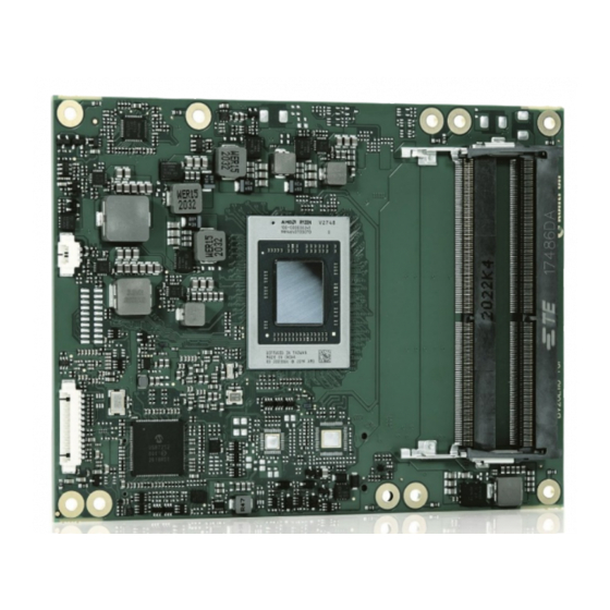
S&T kontron COMe-bV26 Manuals
Manuals and User Guides for S&T kontron COMe-bV26. We have
1
S&T kontron COMe-bV26 manual available for free PDF download: User Manual
S&T kontron COMe-bV26 User Manual (94 pages)
Brand:
S&T
| Category:
Computer Hardware
| Size: 2.89 MB
Table of Contents
Symbols
6
For Your Safety
7
High Voltage Safety Instructions
7
Special Handling and Unpacking Instruction
7
Lithium Battery Precautions
8
General Instructions on Usage
8
Quality and Environmental Management
8
Disposal and Recycling
8
WEEE Compliance
8
Table of Contents
9
List of Tables
11
List of Figures
11
1/ Introduction
13
Product Description
13
Figure 1: COM-Bv26 Front Side
13
Product Naming Clarification
14
Figure 2: COM-Bv26 Rear Side
14
COM Express® Documentation
15
COM Express® Functionality
15
COM Express® Benefits
15
Table 1: Type 6 and COM-Bv26 Functionality
15
2/ Product Specification
17
Module Variants
17
Commercial Grade Modules (0°C to +60°C)
17
Extended Temperature Grade Modules (E1, -25°C to +75°C)
17
Accessories
17
Table 2: Product Number for Commercial Grade Modules (0°C to +60°C Operating)
17
Table 3: Accessories
17
Functional Specification
19
Block Diagram
19
Accelerated Processing Unit (APU)
19
Figure 3: Block Diagram Come-Bv26
19
Fusion Controller Hub (FCH)
20
Table 4: AMD Embedded V-Series Processor Product Family
20
System Memory
21
Graphics
21
Audio
22
PCI Express
22
PCI Express Graphics 3.0 (PEG)
23
USB 3.1. Gen 2/USB 2.0
23
SATA Gen 3.0
24
Ethernet LAN
24
Storage
25
Bios/Software Features
25
Additional Features
25
Electrical Specification
26
Power Supply Specification
26
Table 5: COM-Bv26 Electrical Specification
26
Power Management
27
Power Supply Control
27
Table 6: Power Supply Control Settings
27
Power Supply Modes
28
Table 7: ATX Mode Settings
28
Table 8: Single Power Supply Mode Settings
29
Thermal Management
30
Heatspreader Plate Assembly
30
Active/Passive Cooling Solutions
30
Operating with Kontron Heatspreader Plate (HSP) Assembly
30
Operating Without Kontron Heatspreader Plate (HSP) Assembly
30
Table 9: Heatspreader Temperature Specification
30
Temperature Sensors
31
Figure 4: Module Temperature Sensors
31
On-Module Fan Connector
32
Table 10: Fan Connector (3-Pin) Pin Assignment
32
Figure 5: Fan Connector 3-Pin
32
Environmental Specification
33
Table 11: Environmental Specifications
33
Compliance
34
Mtbf
34
Table 12: CE Compliance
34
Table 13: Country Compliance
34
Table 14: MTBF
34
Figure 6: MTBF De-Rating Values
35
Mechanical Specification
36
Module Dimensions
36
Module Height
36
Figure 7: Module Dimensions
36
Cooling Concept Dimensions
37
Figure 8: Module and Carrier Height
37
Figure 9: Cooling Concept Dimensions
37
3/ Features and Interfaces
38
ACPI Power States
38
Fast I2C
38
Gpio
38
Table 15: Supported Power States Function
38
Hardware Monitor (HWM)
39
Lpc
39
Nvme SSD Flash Memory (Option)
39
Real Time Clock
39
Serial Peripheral Interface
39
SPI Boot
39
Booting the SPI Flash Chip
40
Tpm 2.0
40
Table 16: SPI Boot Pin Configuration
40
Table 17: Supported SPI Boot Flash Types
40
Uart
41
Watchdog Timer (WTD) Dual Stage
41
Table 18: Dual Staged Watchdog Timer- Time-Out Events
41
Watchdog Timer Signal
42
4/ System Resources
43
I2C Bus
43
System Management (SM) Bus
43
Table 19: I2C Bus Port Address
43
Table 20: Smbus Address
43
5/ Come Interface Connector
44
Connecting Come Interface Connector to Carrier Board
44
Figure 10: COM-Bv26 Bottom Side
44
X1A and X1B Signals
45
Table 21: General Signal Description
45
Come Interface Connector (X1A) Pin Assignment
46
Connector X1A Row A1 - A110
46
Table 22: Connector X1A Row A1 to A110 Pin Assignment
46
Connector X1A Row B1 - B110
51
Table 23: Connector X1A Row B1 to B110 Pin Assignment
51
Connector X1B Row C1 - C110
55
Table 24: Connectors X1B Row C1 to C110
55
Connector X1B Row D1 - D110
59
Table 25: Connectors X1B Row D1 to D110
59
6/ Uefi Bios
63
Starting the Uefi BIOS
63
Navigating the Uefi BIOS
63
Table 26: Navigation Hot Keys Available in the Legend Bar
63
Getting Help
64
Setup Menus
64
Figure 11: Setup Menu Selection Bar
64
Main Setup Menu
65
Table 27: Main Setup Menu Sub-Screens and Functions
65
Figure 12: Main Setup Menu
65
Advanced Setup Menu
66
Table 28: Advanced Setup Menu Sub-Screens and Functions
66
Figure 13: Advanced Setup Menu
66
Chipset Setup Menu
82
Table 29: Chipset Setup Menu Sub-Screens and Functions
82
Figure 14: Chipset Setup Menu
82
Security Setup Menu
85
Table 30: Security Setup Menu Sub-Screens and Functions
85
Figure 15: Security Menu Setup
85
Boot Setup Menu
87
Table 31: Boot Setup Menu Sub-Screens and Functions
87
Figure 16: Boot Setup Menu
87
Save and Exit Setup Menu
88
Table 32: Save and Exit Setup Menu Sub-Screens and Functions
88
Figure 17: Save and Exit Setup Menu
88
The UEFI Shell
89
Entering the Uefi Shell
89
Exiting the Uefi Shell
89
Uefi Shell Scripting
90
Startup Scripting
90
Create a Startup Script
90
Example of Startup Scripts
90
Firmware Update
90
7/ Technical Support
91
Warranty
91
Returning Defective Merchandise
92
List of Acronyms
93
Table 33: List of Acronyms
93
About Kontron - Member of the S&T Group
94
Advertisement
Advertisement
Related Products
S&T kontron COMe-cEL6
S&T Kontron COMe-cTL6
S&T kontron COMe-cWL6
S&T kontron COMe-bCL6
S&T Kontron CP3005 Series
S&T Kontron CP3005-SA
S&T Kontron CP3005-V
S&T Kontron SMARC-sXEL
S&T Kontron SL iMX8MM
S&T Kontron VX3060-S2
S&T Categories
Computer Hardware
Switch
Desktop
Motherboard
GPS
More S&T Manuals
Login
Sign In
OR
Sign in with Facebook
Sign in with Google
Upload manual
Upload from disk
Upload from URL