Multitech MultiConnect MicroCell MTCM-LAT3 User Manual
Hide thumbs
Also See for MultiConnect MicroCell MTCM-LAT3:
- Quick start (2 pages) ,
- User manual (39 pages)
Table of Contents
Advertisement
Quick Links
Advertisement
Table of Contents

Related Manuals for Multitech MultiConnect MicroCell MTCM-LAT3


Summary of Contents for Multitech MultiConnect MicroCell MTCM-LAT3
- Page 1 ® MultiConnect MicroCell MTCM-LAT3 and -LSP3 User Guide...
- Page 2 Legal Notices The MultiTech products are not designed, manufactured or intended for use, and should not be used, or sold or re-sold for use, in connection with applications requiring fail-safe performance or in applications where the failure of the products would reasonably be expected to result in personal injury or death, significant property damage, or serious physical or environmental damage.
-
Page 3: Table Of Contents
CONTENTS Contents Chapter 1 – Product Overview ..........................5 About the MultiConnect MicroCell Modem ......................... 5 Dimensions..................................6 LED Descriptions ................................7 MTCM-LAT3 Specifications ............................8 MTCM-LSP3 Specifications............................10 Power Measurements..............................12 MTCM-LAT3 Power Draw............................12 MTCM-LSP3 Power Draw ............................12 Chapter 2 –... - Page 4 CONTENTS Configuring Device as UDP Listener to Accept UDP Client Connections ..............22 Configuring Device as UDP Client to Connect to UDP Server ................... 23 Transferring FTP File to FTP Server ........................... 24 Downloading File from FTP Server..........................25 Reading, Writing and Deleting Messages ........................26 Sending Text Messages .............................
-
Page 5: Chapter 1 - Product Overview
PRODUCT OVERVIEW Chapter 1 – Product Overview About the MultiConnect MicroCell Modem MultiConnect MicroCell 100 Series MTCM CAT 1 cellular modems are ready-to-deploy, standalone LTE UE Category 1 modems that provide wireless communication. The MTCM-LAT3 is a compact communications platform that provides cellular capabilities for fixed and mobile applications. -
Page 6: Dimensions
PRODUCT OVERVIEW Dimensions ® MultiConnect MicroCell MTCM-LAT3 and -LSP3 User Guide... -
Page 7: Led Descriptions
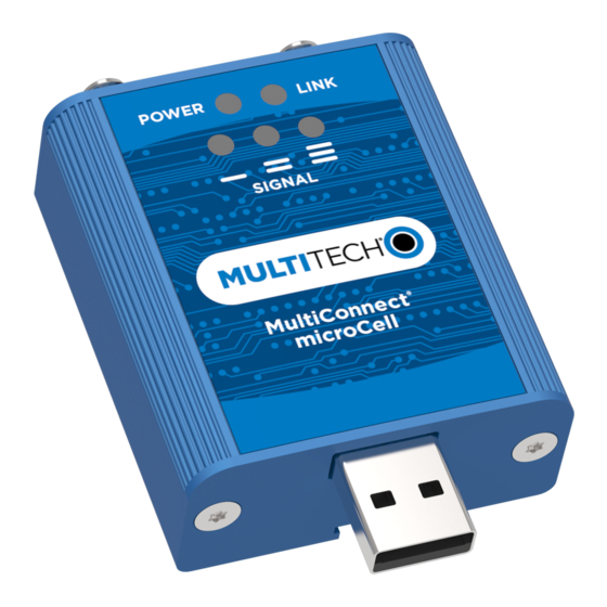
PRODUCT OVERVIEW LED Descriptions The top panel contains the following LEDs: Power LED—The Power LED indicates that DC power is present. Link LED—The Link LED indicated that it is registered on the network. Signal LEDs—Three signal LEDs can display the signal strength level of the wireless connection. LED Indicators POWER Indicates presence of DC power when lit. -
Page 8: Mtcm-Lat3 Specifications
PRODUCT OVERVIEW MTCM-LAT3 Specifications Category Description General Standards LTE 3GPP Release 9 HSPA+ 21/GPRS fallback USB Interface is CDC-ACM compliant TCP/IP Functions FTP, SMTP, SSL, TCP, UDP Frequency Bands 4G: 700 (B12/B13)/850 (B5)/AWS 1700 (B4)/1900 (B2) 3G: 850 (B5)/1900 (B2) Speed Data Speed LTE: 10 Mbps downlink/5 Mbps uplink... - Page 9 PRODUCT OVERVIEW Category Description Radio Compliance FCC Part 22, 24, 27 Safety Compliance UL 60950-1 2nd ED cUL 60950-1 2nd ED IEC 60950-1 2nd ED Network Compliance PTCRB Carrier AT&T ® MultiConnect MicroCell MTCM-LAT3 and -LSP3 User Guide...
-
Page 10: Mtcm-Lsp3 Specifications
PRODUCT OVERVIEW MTCM-LSP3 Specifications Category Description General Standards LTE 3GPP Release 9 HSPA+ 21/GPRS fallback USB Interface is CDC-ACM compliant TCP/IP Functions FTP, SMTP, SSL, TCP, UDP Frequency Bands 4G: 700 (B12/B26)/850 (B5)/AWS 1700 (B4)/1900 (B2) 3G: 850 (B5)/1900 (B2) Speed Data Speed LTE: 10 Mbps downlink/5 Mbps uplink... - Page 11 PRODUCT OVERVIEW Category Description Radio Compliance FCC Part 22, 24, 27 Safety Compliance UL 60950-1 2nd ED cUL 60950-1 2nd ED IEC 60950-1 2nd ED Network Compliance PTCRB Carrier Sprint ® MultiConnect MicroCell MTCM-LAT3 and -LSP3 User Guide...
-
Page 12: Power Measurements
PRODUCT OVERVIEW Power Measurements Multi-Tech Systems, Inc. recommends incorporating a 10% buffer into your power source when determining product load. MTCM-LAT3 Power Draw Radio protocol Sleep mode Live idle No data Max power TX pulse Inrush charge (mA) (mA) (mA) (mA) (mA) (mC) -
Page 13: Chapter 2 - Safety Warnings
SAFETY WARNINGS Chapter 2 – Safety Warnings Radio Frequency (RF) Safety Due to the possibility of radio frequency (RF) interference, it is important that you follow any special regulations regarding the use of radio equipment. Follow the safety advice given below. Operating your device close to other electronic equipment may cause interference if the equipment is inadequately protected. -
Page 14: Antenna
SAFETY WARNINGS Antenna The antenna intended for use with this unit meets the requirements for mobile operating configurations and for fixed mounted operations, as defined in 2.1091 and 1.1307 of the FCC rules for satisfying RF exposure compliance. If an alternate antenna is used, consult user documentation for required antenna specifications. ®... -
Page 15: Chapter 3 - Installing And Using The Device
INSTALLING AND USING THE DEVICE Chapter 3 – Installing and Using the Device Installing the Device Connect antennas to the antenna connectors. Connect the USB connector to your computer or other USB high power device, such as a hub. The POWER LED lights after the device powers up. Powering Down Your Device CAUTION: Failing to properly power down the device before removing power may corrupt your device's file... - Page 16 INSTALLING AND USING THE DEVICE To secure the bracket to the desired surface, place and tighten two screws in the holes on either end of the mounting bracket. The dimensions illustration in this guide shows the mounting bracket, as well as the dimensions for placement of the screws.
-
Page 17: Chapter 4 - Antenna And Activation Information
ANTENNA AND ACTIVATION INFORMATION Chapter 4 – Antenna and Activation Information Antenna The antenna intended for use with this unit meets the requirements for mobile operating configurations and for fixed mounted operations, as defined in 2.1091 and 1.1307 of the FCC rules for satisfying RF exposure compliance. If an alternate antenna is used, consult user documentation for required antenna specifications. -
Page 18: Device Phone Number
All applications interacting with Sprint approved MultiTech devices must be written in a manner where they do not interfere/interrupt the Sprint Hands-Free Activation (HFA) process or OMA-DM processes. If the MultiTech device will be co-located with any other transmitters you will be required to submit your device to an FCC approved lab for additional testing. -
Page 19: Chapter 5 - Configuring And Communicating With Your Device
CONFIGURING AND COMMUNICATING WITH YOUR DEVICE Chapter 5 – Configuring and Communicating with Your Device Before Using the Device Before using the device: Install any drivers. Refer to the separate driver installation guide for your device. Power up your device and ensure it is connected to your computer that issues AT commands. Note: Wait 10 seconds after power-up before issuing any AT commands. -
Page 20: Example
CONFIGURING AND COMMUNICATING WITH YOUR DEVICE <rssi> Received signal strength indication. (-113) dBm or less (-111) dBm 2-30 (-109) dBm - (-53) dBm / 2 dBm per step (-51) dBm or greater Not known or not detectable <sq> LTE - RSRQ (in dBm): -4 to -3 -6 to -5 -8 to -7... -
Page 21: Sending And Receiving Data
CONFIGURING AND COMMUNICATING WITH YOUR DEVICE The device is registered. If the device returns: +CEREG: 0,2 The device is in a network searching state. If the device returns: +CEREG: 0,3 The registration is denied. If the device returns: +CEREG: 0,0 The device is not currently attempting to register to a network. -
Page 22: Configuring Device As Udp Listener To Accept Udp Client Connections
CONFIGURING AND COMMUNICATING WITH YOUR DEVICE AT#SH=1 To close the data connection: Enter: AT#SGACT=1,0 The device responds with OK. Configuring Device as UDP Listener to Accept UDP Client Connections To configure the device as a UDP client: Check signal strength. Enter: AT+CSQ Verify device is registered on the cellular network. -
Page 23: Configuring Device As Udp Client To Connect To Udp Server
CONFIGURING AND COMMUNICATING WITH YOUR DEVICE Exit Data Mode and Close Connection To exit data mode and close the socket: Enter the escape sequence: To close Socket 1, enter: AT#SH=1 To close the data connection, enter: AT#SGACT=1,0 The device responds with OK. Configuring Device as UDP Client to Connect to UDP Server Configure and Connect the Device To configure the device as a UDP client:... -
Page 24: Transferring Ftp File To Ftp Server
CONFIGURING AND COMMUNICATING WITH YOUR DEVICE AT#SGACT=1,0 The device responds with OK. Transferring FTP File to FTP Server To connect to FTP server and upload files: Check signal strength. Enter: AT+CSQ Verify device is registered on the cellular network. Enter: AT+CEREG? Should return: +CEREG: 0,1 or +CEREG: 0,5... -
Page 25: Downloading File From Ftp Server
CONFIGURING AND COMMUNICATING WITH YOUR DEVICE Close the FTP connection. Enter: AT#FTPCLOSE Close the PPP data connection. Enter: AT#SGACT=1,0 The device responds with OK. Downloading File from FTP Server To connect to an FTP server and download files: Check signal strength. Enter: AT+CSQ Verify device is registered on the cellular network. -
Page 26: Reading, Writing And Deleting Messages
CONFIGURING AND COMMUNICATING WITH YOUR DEVICE The file is received through the device. The device responds with: NO CARRIER The data connection closes automatically when the file sending ends. Closing the FTP Data Connection After the file is sent: Close the FTP connection. Enter: AT#FTPCLOSE Close the PPP data connection. -
Page 27: Reading Text Messages
CONFIGURING AND COMMUNICATING WITH YOUR DEVICE where # is the reference number of the sent message. For example: AT+CMGF=1 AT+CMGS="0001112222" > How are you? <CTRL+Z to send> +CMGS: 255 Where 0001112222 is the phone number. Reading Text Messages To read a text message in text mode: Send a message to the phone number of the currently installed SIM. - Page 28 CONFIGURING AND COMMUNICATING WITH YOUR DEVICE AT+CMGD=1 (delete message at index 1) AT+CMGD=2 (delete message at index 2 ) AT+CMGD=1,0 AT+CMGD=1,1 AT+CMGD=1,2 AT+CMGD=1,3 AT+CMGD=1,4 ® MultiConnect MicroCell MTCM-LAT3 and -LSP3 User Guide...
-
Page 29: Chapter 6 - Regulatory Information
REGULATORY INFORMATION Chapter 6 – Regulatory Information Industry Canada Class B Notice This Class B digital apparatus meets all requirements of the Canadian Interference-Causing Equipment Regulations. Cet appareil numérique de la classe B respecte toutes les exigences du Reglement Canadien sur le matériel brouilleur. -
Page 30: Restriction Of The Use Of Hazardous Substances (Rohs)
2011/65/EU of the European Parliament (Restriction of the use of certain Hazardous Substances in electrical and electronic equipment - RoHS). These MultiTech products do not contain the following banned chemicals Lead, [Pb] < 1000 PPM Mercury, [Hg] <... -
Page 31: Information On Hs/Ts Substances According To Chinese Standards
REGULATORY INFORMATION Information on HS/TS Substances According to Chinese Standards In accordance with China's Administrative Measures on the Control of Pollution Caused by Electronic Information Products (EIP) # 39, also known as China RoHS, the following information is provided regarding the names and concentration levels of Toxic Substances (TS) or Hazardous Substances (HS) which may be contained in Multi-Tech Systems Inc. -
Page 32: Information On Hs/Ts Substances According To Chinese Standards (In Chinese)
REGULATORY INFORMATION Information on HS/TS Substances According to Chinese Standards (in Chinese) 依 依 照 照 中 中 国 国 标 标 准 准 的 的 有 有 毒 毒 有 有 害 害 物 物 质 质 信 信 息 息 根据中华人民共和国信息产业部... -
Page 33: Chapter 7 - Connection Manager Overview
Follow these steps in order. Attempting to plug in the device before the appropriate drivers are installed can cause the connection to fail. Go to www.multitech.com/connectionmanager.go. Click Connection Manager. Open or unzip the Connection Manager file and run the installer (.msi file). -
Page 34: Setting Up A Serial Device
CONNECTION MANAGER OVERVIEW Browse to a website to confirm the device has Internet access. Setting Up a Serial Device Connect the serial device to the PC. Navigate to Control Panel > Device Manager. Make note of the COM port number for the connected device (in COM Ports). - Page 35 CONNECTION MANAGER OVERVIEW Click Browse and select the installation folder. Example: C:\Program Files (x86)\Multi-Tech Systems\Multi-Tech Connection Manager. The list of available TELIT models appears. Select the model number for your device, then click Next. ® MultiConnect MicroCell MTCM-LAT3 and -LSP3 User Guide...
-
Page 36: Troubleshooting
CONNECTION MANAGER OVERVIEW Select the COM port that you noted from COM ports, then click Next. Click Finish to exit the Wizard. Navigate to Device Manager > Modems and confirm that the device is added. Troubleshooting Serial COM port is not available in the Serial Modem Settings This can happen if the modem was installed while Connection Manager was running. -
Page 37: Multiconnect Cell Usb Modem Is Not Detected
CONNECTION MANAGER OVERVIEW Restart Connection Manager. Disconnect and reconnect the device. MultiConnect Cell USB Modem is not detected Check the Power and LS LEDs on the device. If they are not continuously lit, then the problem is with the power supply. Check the cable and connections. USB device: Make sure that the device is connected to the PC and that the correct USB cable is in use.
Need help?
Do you have a question about the MultiConnect MicroCell MTCM-LAT3 and is the answer not in the manual?
Questions and answers