
Subscribe to Our Youtube Channel
Related Manuals for Multitech MultiModem MTCBA-E-GP


Summary of Contents for Multitech MultiModem MTCBA-E-GP
- Page 1 MultiModem Wireless Modems EDGE, GPRS, CDMA with GPS Functionality MTCBA-E-GP MTCBA-G-GP-Fx MTCBA-C-GP-Nx User Guide...
- Page 2 Technical Support Country By Email By Phone France support@multitech.fr +(33) 1-64 61 09 81 India support@multitechindia.com +(91) 124-2340780 Europe, Asia, Africa support@multitech.co.uk +(44) 118 959 7774 U.S., Canada, all others...
-
Page 3: Table Of Contents
Table of Contents Table of Contents Chapter 1 – Introduction and Product Description ................... 4 GPS Interface................................4 MultiModem EDGE ..............................4 MultiModem GPRS ..............................4 MultiModem CDMA ..............................4 Safety Warnings ...............................5 General Safety..............................5 Vehicle Safety..............................5 Maintenance of the Wireless MultiModem .......................5 Handling Precautions............................5 Safety Recommendations for Rack Installations....................6 Ship Kit Contents ..............................6 Wireless Modem Specifications..........................7... -
Page 4: Chapter 1 - Introduction And Product Description
Chapter 1 – Introduction and Product Description Chapter 1 – Introduction and Product Description This User Guide describes the MultiModem Wireless EDGE, GPRS, and CDMA modems with GPS functionality. Your product choice depends on the technology (cellular network) available to you. Product Your Cellular Network Interface... -
Page 5: Safety Warnings
Chapter 1 – Introduction and Product Description Safety Warnings General Safety The modem is designed and intended to be used in either fixed or mobile applications. In the “Fixed” application, the device is physically secured at one location and not easily moved to another location. In the “Mobile” application, the device may be regularly moved to different locations. -
Page 6: Safety Recommendations For Rack Installations
Chapter 1 – Introduction and Product Description Safety Recommendations for Rack Installations • Ensure proper installation in a closed or multi-unit enclosure by following the recommended installation as defined by the enclosure manufacturer. • If installing the wireless modem in a closed or multi-unit enclosure, ensure adequate airflow so that the maximum recommended ambient temperature is not exceeded. -
Page 7: Wireless Modem Specifications
Chapter 1 – Introduction and Product Description Wireless Modem Specifications Features EDGE Modem GPRS Modem CDMA Modem Performance EDGE: E-GPRS Class 10 GPRS Class 10 CDMA2000 1xRTT GPRS: Class 12 Band, Quad-band GSM Dual-band 850/1900 or 900/1800 Dual-band 800/1900 MHz CDMA; Frequency 850/900/1800/1900 MHz MHz GSM/GPRS... -
Page 8: Gps Specifications
Chapter 1 – Introduction and Product Description GPS Specifications Key Features • 12-channel simultaneous operation • Dual sensitivity modes with automatic switching • Aided GPS through TSIP • Antenna open and short circuit detection and protection • Supports NMEA 0183, TSIP, and TAIP, DGPS protocols •... -
Page 9: The Front Panel
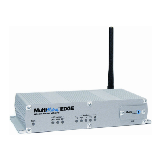
Chapter 1 – Introduction and Product Description The Front Panel The MultiModem wireless EDGE modem with GPS functionality has 8 LEDs, 5 of which are modem LEDs, and a SIM card. The MultiModem wireless GPRS modem with GPS functionality has the same LEDs and SIM card as the EDGE modem. -
Page 10: Chapter 2 - Setup And Configuration
Chapter 2 – Setup and Configuration Chapter 2 – Setup and Configuration Back Panel of the MultiModem with GPS The back panel view is included to help you understand the MultiModem setup. MultiModem with GPS Interface Back Panel S1/S2 Switches Note: The switches as shown in the diagram above are located behind a cover plate that can be removed when you need to change the switch settings. -
Page 11: Sim Card For Gprs Or Edge
Chapter 2 – Setup and Configuration 2. SIM Card for GPRS or EDGE The wireless modem requires the power supply connection to begin operation. It also requires a SIM card (Subscriber Identity Module) to operate on a GPRS or EDGE network. To install the SIM card: Use a small screwdriver to remove the screw closest to the outside edge of the modem. -
Page 12: Login Using Tty
Chapter 2 – Setup and Configuration 5. Login Using TTY • Use TTY to configure your IP module for the first time. Configure the host serial port using the defaults listed below: Baud: 115.2K Data: 8 Parity: N Stop: 1 Flow-Control: None •... -
Page 13: Configuring The Gps Side Of The Multimodem
Chapter 2 – Setup and Configuration Configuring the GPS Side of the MultiModem 1. Port Configuration The GPS receiver module has two I/O ports. The table below provides the default protocols and port configurations for the receiver, as delivered from the factory. TSIP IN/OUT is the default protocol on Port 1 and RTCM-IN and NMEA-OUT is the default protocol on Port 2. -
Page 14: Hardware Setup
Chapter 2 – Setup and Configuration 2. Hardware Setup Using an RS-232 cable, connect a workstation to the GPS connector on the MultiModem. Attach both antennas (included in your ship kit). The GPS antenna is a 50 ohm SMA antenna. The GSM/ CDMA antenna is a standard SMA antenna. -
Page 15: Chapter 3 - Setup/Configuration Examples
Chapter 3 – Setup/Configuration Examples Chapter 3 – Setup/Configuration Examples Application Example 1 In this example, the GPS side of the MultiModem is monitoring GPS locations and the wireless modem side of the MultiModem is waiting for incoming data. A portable workstation, such as a laptop or handheld PC, is connected to this wireless modem to both serial ports –... -
Page 16: Application Example 2
Chapter 3 – Setup/Configuration Examples Application Example 2 This example shows the MultiModem GRPS Wireless Modem with GPS mounted in a truck that can be tracked by a GPS satellite. This configuration shows a MultiModem located in a vehicle and not connected to a portable PC. The MultiModem in this example simply reads the GPS data as it is sent from GPS satellite, and then it broadcasts the data to your central tracking system by way of your CDMA, GPRS, or EDGE network provider connection. -
Page 17: Chapter 4 - Antennas And Cables
Chapter 4 – Antennas and Cables Chapter 4 – Antennas and Cables The Antenna The antenna sub-system and integration in the application is a major issue: Choice of antenna (type, length, performances, thermal resistance, etc.) These elements could affect GSM performances such as sensitivity and emitted power. -
Page 18: Gps Antenna Compact Magnetic Mount Antenna
Chapter 4 – Antennas and Cables GPS Antenna Compact Magnetic Mount Antenna Antenna Frequency Range 1,575.42+/-1.023MHz Gain 90°: 3.0dBi min.; 20°: -4.0dBi min. (mounted on the 65mm X 65mm square ground plane) Polarization RHCP Axial Ratio 90°: 4.0dB max.; 10°: 6.0dB max. (mounted on the 65mm X 65mm square ground plane) Frequency Range 1,575.42 ±1.023MHz... - Page 19 Chapter 4 – Antennas and Cables Multi-Tech Systems, Inc. MultiModem Wireless EDGE, GPRS, and CDMA Modems with GPS (S000376A)
-
Page 20: Serial Cable For Multimodem Gps
Chapter 4 – Antennas and Cables Serial Cable for MultiModem GPS DE-9P DE-9S Fused Cable for MultiModem GPS Recommended Replacement Fuses Manufacturer: Littelfuse Part Number: 313 02.5 Manufacturer: Sun Fuse Part Number: 6S Multi-Tech Systems, Inc. MultiModem Wireless EDGE, GPRS, and CDMA Modems with GPS (S000376A) -
Page 21: Fused Cable Dimensions
Chapter 4 – Antennas and Cables Fused Cable Dimensions Includes: How to Change the Fuse Multi-Tech Systems, Inc. MultiModem Wireless EDGE, GPRS, and CDMA Modems with GPS (S000376A) -
Page 22: Appendix A - Multi-Tech Systems, Inc. Warranty And Repair Policies
Please direct your questions regarding technical matters, product configuration, verification that the product is defective, etc., to our Technical Support department at (800) 972-2439 or email support@multitech.com. Please direct your questions regarding repair expediting, receiving, shipping, billing, etc., to our Repair Accounting department at (800) 328-9717 or (763) 717-5631, or email mtsrepair@multitech.com. -
Page 23: Repair Procedures For International Distributors
Please direct your questions regarding technical matters, product configuration, verification that the product is defective, etc., to our Technical Support department nearest you or email support@multitech.com. When calling the U.S., please direct your questions regarding repair expediting, receiving, shipping, billing, etc., to our Repair Accounting department at +(763) 717-5631 in the U.S.A., or email mtsrepair@multitech.com. -
Page 24: Appendix B - Waste Electrical And Electronic Equipment
Appendix B – Waste Electrical and Electronic Equipment Appendix B – Waste Electrical and Electronic Equipment Waste Electrical and Electronic Equipment (WEEE) The WEEE directive places an obligation on EU-based manufacturers, distributors, retailers and importers to take- back electronics products at the end of their useful life. A sister Directive, ROHS (Restriction of Hazardous Substances) complements the WEEE Directive by banning the presence of specific hazardous substances in the products at the design phase. -
Page 25: Index
Index Index Antennas ............17, 18 Network Registration Check........12 AT Commands ............4 NMEA 0183..............4 Back Panel ...............10 Ordering Replacement Parts........23 CDMA ................4 port configurations............13 CDMA200 1xRTT............4 Power source warning........10, 14 Changing the Fuse...........21 Compact Magnetic Mount Antenna ......18 Customer Activation Notices ........6 Rack Installation Safety..........6 Radio Characteristics ..........17 real-time tracking server..........4...
Need help?
Do you have a question about the MultiModem MTCBA-E-GP and is the answer not in the manual?
Questions and answers