Advertisement
Quick Links
A Capital Safety Company
FORM NO: 5902228
REV: O
USER INSTRUCTIONS
x1-4
East Kilbride,
CE TYPE TEST
CE
BSI Product Services
Kitemark House
PRODUCTION
QUALITY
Mayland Ave.
CONTROL
Hemel Hempstead
4
5
7
8
9
10
2
Flexible Cable Ladder Safety Systems
I S O
No. 0320
9 0 0 1
TUV NEL
Certificate No. FM 39709
Glasgow
G75 0QU
UK
11
No. 0086
AS/NZS
HP2 4SQ UK
12
6
LAD-SAF
®
1
3
ANSI Z359
ANSI A14.3
EN 353-1:2002
CSA Z259.2.1
AS/NZS 1891.3:1997
© Copyright 2009, DB Industries, Inc.
Advertisement

Related Manuals for DBI SALA LAD-SAF


Summary of Contents for DBI SALA LAD-SAF
- Page 1 LAD-SAF ® USER INSTRUCTIONS Flexible Cable Ladder Safety Systems x1-4 A Capital Safety Company I S O ANSI Z359 No. 0320 9 0 0 1 TUV NEL ANSI A14.3 Certificate No. FM 39709 East Kilbride, CE TYPE TEST Glasgow G75 0QU EN 353-1:2002 No.
- Page 3 Follow the manufacturer’s instructions for safety equipment used with this system. Follow these instructions for proper use, inspection, and maintenance of this equipment. This equipment is intended to be used as part of a complete LAD-SAF ladder safety system. Alterations, ®...
- Page 4 Figure 1: Part List TB - Top Brackets ITEM ANSI, CSA, AS/NZS DESCRIPTION TB-1 6116054 6116054 Top Bracket Galvanized TB-2 6116056 KC36116056 Top Bracket Galvanized 6116280 KC3PL280 Top Bracket Galvanized TB-3 6116278 6116278 Top Bracket Galvanized, 8 mm TB-4 6116210 KC3PL210 Top Bracket Stainless Steel TB-5...
- Page 5 Figure 1 (continued): Part List TB - Top Brackets ITEM ANSI, CSA, AS/NZS DESCRIPTION TB-8 6116120 6116120 Top Bracket, Galvanized, Telescoping 6116005 KC36110020 Top Bracket, Stainless Steel for 1-1/4” rung (2 clamps) 6116050 6116050 Top Bracket, Galvanized for 2” x 1-1/2” rung TB-9 6116052 6116052...
- Page 6 Figure 1 (continued): Part List TB - Top Brackets ITEM ANSI, CSA, AS/NZS DESCRIPTION 6116048 6116048 Top Bracket, Galvanized for 1-1/2” x 1-1/2” angle x 30 6116051 6116051 Top Bracket, Galvanized for 1-1/4” angle 6116055 6116055 Top Bracket, Galvanized for 1” x 3/4” angle TB13 6116057 6116057...
- Page 7 Figure 2: Part List BB - Bottom Brackets ITEM ANSI, CSA, AS/NZS DESCRIPTION 6100090 KC3PL90 Bottom Bracket, Galvanized 6100091 KC36100091 Bottom Bracket, Galvanized, Extra-Long BB-1 6100092 6100092 Bottom Bracket, Galvanized, 37” 6100093 6100093 Bottom Bracket, Galvanized, 48” 6100060 6100060 Bottom Bracket, Galvanized for 2” x 1-1/4” rung 6100070 6100070 Bottom Bracket, Stainless Steel...
- Page 8 Figure 2 (continued): Part List BB - Bottom Brackets ITEM ANSI, CSA, AS/NZS DESCRIPTION 6100035 KC36100035 Bottom Bracket, Galvanized BB-7 6100038 KC36100038 Bottom Bracket - Stainless Steel BB-8 6100045 6100045 Bottom Bracket, Galvanized 6100050 6100050 Bottom Bracket, Galvanized for 1-5/8” x 1-3/8” rung 6100055 6100055 Bottom Bracket, Galvanized for 1-1/2”...
- Page 9 Figure 3: Part List CG - Cable Guides ITEM ANSI, CSA, AS/NZS DESCRIPTION CG-1 6100249 6100249 Cable Guide, Stainless Steel, 45 bend CG-2 6100140 6100140 Cable Guide 6100400 KC3PL330 Cable Guide, Galvanized CG-3 6100401 6100401 Cable Guide, Stainless Steel 6100402 6100402 Cable Guide, Galvanized, 1-3/4”...
- Page 10 Figure 3 (continued): Part List CG - Cable Guides ITEM ANSI, CSA, AS/NZS DESCRIPTION 6100460 6100460 Cable Guide, Stainless Steel, w/Twist 39 CG-10 6100461 6100461 Cable Guide, Stainless Steel, w/Twist 27 6100462 6100462 Cable Guide, Stainless Steel, w/Twist 45 CG-11 6100475 6100475 Cable Guide, Stainless Steel, 1-1/2”...
- Page 11 Figure 4: Part List SO - Stand-Offs ITEM ANSI, CSA, AS/NZS DESCRIPTION SO-1 Top/Bottom Bracket Horizontal Stand-Off SO-2 6100710 KC36100710 Top/Bottom Bracket Weld-On Stand-Off SO-3 Cable Guide Round Leg Stand-Off Support 6100600 6100600 Top/Bottom Bracket Angle Stand-Off, 60 angle, 2” - 2-1/2” angle size, Stainless Steel 6100601 6100601 Top/Bottom Bracket Angle Stand-Off, 60...
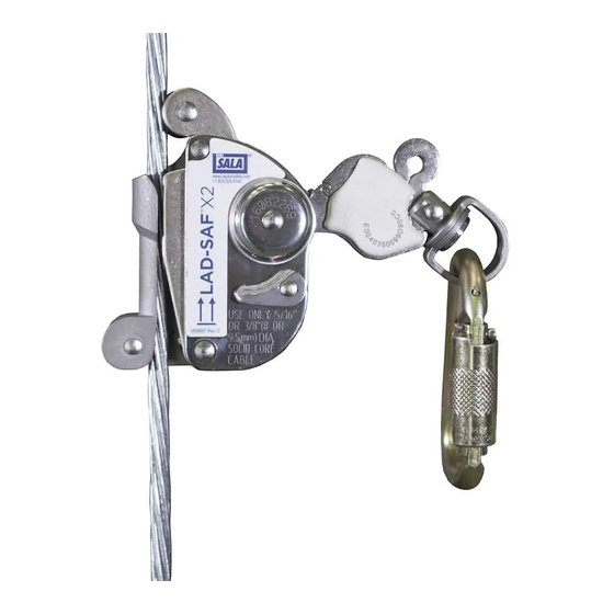
- Page 12 Figure 5: Part List LS - LAD-SAF Detachable Sleeves ® ITEM ANSI, CSA DESCRIPTION 6116541 Flex Sleeve, 8.0 mm or 9.5 mm (5/16” or 3/8”), Sleeve Only LS-1 (ANSI A14.3, CSA Z259.2.1) LS-2 6116540 Flex Sleeve, 8.0 mm or 9.5 mm (5/16” or 3/8”), w/Carabiner (ANSI A14.3, CSA Z259.2.1)
-
Page 13: System Requirements
LAD-SAF Detachable Sleeve and may result ® in failure to arrest a fall. Avoid connecting the sleeve used on the LAD-SAF Ladder System into the ® same harness connection D-ring as is occupied by the climb assist system. Ensure that movement of... -
Page 14: System Installation
Use caution when installing LAD-SAF systems near electrical power lines. ® LAD-SAF cables are conductive. Do not connect to a partially installed LAD-SAF system. ® ® 3.2 WELDING RECOMMENDATIONS: Some installations require welding brackets to the structure. DBI-SALA recommends that welding be completed by a certifi... - Page 15 3.3 TOP BRACKET INSTALLATION: Before Figure 6 - Installing Top Brakcets installing the top bracket it is recommended that the ladder or climbing structure be evaluated by a qualifi ed engineer to determine if the load requirements for the system are satisfi ed. Height above A.
- Page 16 Figure 8 - Ladder Rung Support Piece 17” (43 cm) Max outside dimension...
- Page 17 The ladder or climbing structure must be evaluated by a qualifi ed engineer to determine if the load requirements for the system with rung supports are satisfi ed. Install ladder rung support at each LAD-SAF component ® connection point.
- Page 18 Figure 10 - Installing Curved Ladder Top Brackets TB-12 Top Bracket TB-11 Top Bracket Installation Installation Figure 11 - Installing Bolt-on Top Bracket & Weld-on Stand-off 1-1/8” (2.86 cm) SO-2 Stand-Off Installation TB-4, TB-6, TB-7 Top Brackets with SO-2 Stand-Off Installation Angle Leg and Round Leg Stand-off Installation: See Figure 12 for the installation of the angle and round leg stand-off supports.
- Page 19 WARNING: Installations that use the angle Figure 12 - Installing Angle Leg & Round Leg Stand-offs leg or round leg stand-off support brackets are limited to one user on the system at a time. E. INSTALLATION OF TB-5 WOOD POLE TOP BRACKET: See Figure 13 for a typical installation of the TB-5 top bracket onto a wooden pole.
- Page 20 Secure the front attachment point on a full body harness to the carrier cable with a Lad-Saf detachable cable sleeve ® TB-8 Top Bracket and climb up and down the ladder. (See the Lad-Saf Detachable ® Installation Cable Sleeve User Instruction Manual for details). When you are done rotate the bracket handle counterclockwise and allow the bracket to slide back down into the stationary bracket.
- Page 21 3.4 INSTALLATION OF CARRIER CABLE TO TOP BRACKET: Keep the carrier cable and carrier clamp clean during installation. Contamination of WARNING: the carrier clamp or cable could cause the clamp to malfunction. A. INSTALLATION OF GALVANIZED CARRIER CABLE: 1. Lay the carrier cable out on the ground in a clean area by rolling the coil. Do not pull cable from center of coil.
- Page 22 3.5 INSTALLATION OF CABLE GUIDES, ALL MODELS: Figure 19 - Installing Cable Cable guides protect the carrier cable from chafi ng against the Guides ladder or structure and to prevent the climber from excessively defl ecting the cable from side to side. Cable guides should be positioned at approximately 25 ft (7.62 m) intervals along the carrier cable between the top and bottom brackets, and at any point along the system where the cable may abrade against the...
- Page 23 3.6 INSTALLATION OF BOTTOM BRACKET AND Figure 22 - Installing Bottom CARRIER CABLE TENSION ADJUSTMENT: Brackets Before installing the bottom bracket it is recommended that the ladder and/or climbing structure be evaluated by a qualifi ed engineer to determine if the load requirements for the system specifi...
- Page 24 Figure 24 - Installing Bottom Brackets Compress Compress to 5-1/2” to 5-1/2” (14 cm) (14 cm) BB-4 Bottom Bracket BB-6 Bottom Bracket Installation Installation B. INSTALLATION OF BB-4, BB-5, AND BB-6 BOTTOM BRACKETS: Bottom Bracket Installation: See Figure 24 for a typical installations of the BB-4 and BB-6 bottom brackets onto a round rung ladder. See Figure 25 for a typical installation of the BB-5 bottom bracket with a weld-on stand-off support.
- Page 25 SO-2 Stand-Off Installation structure using a DBI-SALA or customer supplied stand-off support. Customer supplied stand-off supports must be capable of withstanding the loads specifi ed in section 2.3 and must be compatible with the LAD-SAF system. ® Weld-on Stand-off Installation: Install the SO-2 stand-off support as Figure 27 - Installing Angle Leg &...
- Page 26 B. After installation conduct a fi nal inspection of the system as follows: • Ensure all fasteners are in place and properly tightened. • Ensure the carrier cable is properly tensioned. Do not use the Lad-Saf system if the bottom of the ®...
- Page 27 The user may not be protected against hitting the ground or landing during the fi rst 7 ft. (2 m) of ascent or last 7 ft. (2 m) of descent. Extra care should be taken when ascending or descending the portion of the ladder below the bottom bracket of the Lad-Saf™ system. •...
- Page 28 5.3 INSPECTION GUIDELINES - LAD SAF DETACHABLE CABLE SLEEVE: ® Inspect the LAD-SAF detachable sleeve per the inspection steps defi ned in the associated User ® Instructions. See Figure 5 for a listing of LAD-SAF sleeve models and their respective User Instructions. ®...
-
Page 29: Specifications
7.0 SPECIFICATIONS 7.1 All top and bottom brackets, cable guides, carrier cable, and fasteners are made of galvanized or stainless steel. Contact DBI-SALA for material specifi cation details if required. The LAD-SAF system, when installed ® according to the user instructions, meets OSHA, ANSI (ANSI A14.3), CSA (Z259.2.1), CE (EN 353-1:2002), and AS/NZS (AS/NZS 1891.3:1997) requirements. -
Page 30: Installation Checklist
Ensure system information is recorded on the system label and Inspection and Maintenance Log: Components of the LAD-SAF system include an i-Safe™ Radio Frequency (RFID) tag. The RFID tag can be used in conjunction with the i-Safe handheld reading device and web based portal (www.capitalsafety/isafe).to simplify inspection and inventory control and maintain electronic records for your fall protection equipment. - Page 31 Ensure system information is recorded on the system label and Inspection and Maintenance Log: Components of the LAD-SAF system include an i-Safe™ Radio Frequency (RFID) tag. The RFID tag can be used in conjunction with the i-Safe handheld reading device and web based portal (www.capitalsafety/isafe).to simplify inspection and inventory control and maintain electronic records for your fall protection equipment.
- Page 32 Ensure system information is recorded on the system label and Inspection and Maintenance Log: Components of the LAD-SAF system include an i-Safe™ Radio Frequency (RFID) tag. The RFID tag can be used in conjunction with the i-Safe handheld reading device and web based portal (www.capitalsafety/isafe).to simplify inspection and inventory control and maintain electronic records for your fall protection equipment.
-
Page 33: Inspection And Maintenance Log
INSPECTION AND MAINTENANCE LOG Serial Number(s): Model Number(s): Date Purchased: Date of First Use: Inspect Top and Bottom Brackets: Inspect for damage, corrosion, or rust. Look for cracks, bends, or Date: wear that could affect strength and operation. Inspect for missing fasteners; retighten or replace as necessary. Inspect Cable Guides: Ensure cable guide is not warn or bent and still locks onto the cable. - Page 34 INSPECTION AND MAINTENANCE LOG Serial Number(s): Model Number(s): Date Purchased: Date of First Use: Inspect Top and Bottom Brackets: Inspect for damage, corrosion, or rust. Look for cracks, bends, or Date: wear that could affect strength and operation. Inspect for missing fasteners; retighten or replace as necessary. Inspect Cable Guides: Ensure cable guide is not warn or bent and still locks onto the cable.
- Page 35 INSPECTION AND MAINTENANCE LOG Serial Number(s): Model Number(s): Date Purchased: Date of First Use: Inspect Top and Bottom Brackets: Inspect for damage, corrosion, or rust. Look for cracks, bends, or Date: wear that could affect strength and operation. Inspect for missing fasteners; retighten or replace as necessary. Inspect Cable Guides: Ensure cable guide is not warn or bent and still locks onto the cable.
- Page 36 A Capital Safety Company CSG USA CSG Canada Ltd. CSG Northern Europe Ltd. 3833 Sala Way 60 Export Boulevard 7 Christleton Court • Stuart Rd. Red Wing, MN 55066-5005 Mississauga, Ontario L5S 1Y9 Manor Park • Runcorn Canada Cheshire WA7 1ST • UK Toll Free: 800.328.6146 Toll Free: 800.387.7484 Phone: +44 (0) 1928 571324...
Need help?
Do you have a question about the LAD-SAF and is the answer not in the manual?
Questions and answers