Table of Contents

Related Manuals for TERSUS PRECIS-TX204


Summary of Contents for TERSUS PRECIS-TX204
-
Page 1: User Manual
User Manual Version V1.0-20170511 Precis-TX204 GNSS Receiver ©2017 Tersus GNSS Inc. All rights reserved. Sales & Technical Support: sales@tersus-gnss.com & support@tersus-gnss.com More details, please visit www.tersus-gnss.com... -
Page 2: Table Of Contents
Battery and Power ....................16 External Power ......................16 Charging the Battery ....................16 Removing the Battery ....................16 Set up Precis-TX204 GNSS Receiver ..............17 Turn on/off the Receiver ..................17 Guidelines for Setting up the Receiver ..............17 Environmental Conditions ..................17 4.2.1... - Page 3 Position........................22 5.3.1.1 Activity ........................23 5.3.1.2 Google Map ......................24 5.3.1.3 Satellites Menu ......................24 5.3.2 Satellite Tracking Graph ..................24 5.3.2.1 Satellite Tracking Graph ..................25 5.3.2.2 Tracking Skyplot ...................... 25 5.3.2.3 Satellite Activation ....................26 5.3.2.4 Receiver Configuration Menu .................. 26 5.3.3 Receiver Summary ....................
- Page 4 Firmware Info ......................43 5.3.8.2 System Log ......................44 5.3.8.3 Firmware Update ...................... 44 5.3.8.4 Config File ....................... 44 5.3.8.5 GNSS Registration ....................45 5.3.8.6 The Hardware Version ..................... 45 5.3.8.7 Upgrade Online ......................46 5.3.8.8 User log ........................46 5.3.8.9 Appendix ........................
- Page 5 List of Figures Figure 1 Outlook of Precis-TX204 GNSS receiver ..............7 Figure 2 Standard package of Precis-TX204 ................11 Figure 3 Outlook of helix antenna ..................11 Figure 4 Outlook of adapter ....................12 Figure 5 Outlook of shoulder-strap ..................12 Figure 6 Outlook of front panel ....................
- Page 6 Figure 44 APIS_BASE setting page ..................37 Figure 45 TCP/UPD client setting page .................. 37 Figure 46 NTRIP server setting page ..................38 Figure 47 TCP server setting page ..................38 Figure 48 BlueTooth port setting page ..................39 Figure 49 Network Set menu ....................39 Figure 50 Network information ....................
- Page 7 List of Tables Table 1 Features of TX204 ......................7 Table 2 TX204 models ......................9 Table 3 Description of power LED and button of front panel ..........13 Table 4 Description of power LED and button of back panel ..........14 Table 5 Description of ports on the adaptor ................
-
Page 8: Introduction
1 Introduction Precis-TX204 is an integrated multi-GNSS receiver, which is light-weight, rugged with built-in centimeter accurate RTK engine, onboard storage and versatile connectivity. The TX204 rear panel also features Light Emitting Diodes (LEDs) for status indication. After powered on, the TX204 begins operating as a fully functional GNSS system. -
Page 9: Other Features
Size L*W*H 110*81*52 (battery included) Weight 489g (battery included), 250g (battery excluded) Battery type Removable lithium battery Battery capacity 7.4V 4300mAH Charging time 4hour (typical) Internal flash size 16GB 12 hours (GNSS only) 11hours (GNSSS + BlueTooth) Operating time 10 hours (GNSS + Wi-Fi) 8hours (GNSS + cellular module) Communication &... -
Page 10: Typical Application Of Tx204 Receiver
Table 2 TX204 models Model Name Description TX204B Supporting GPS L1/L2, GLONASS G1, Beidou B1/B3 TX204G Supporting GPS L1/L2, GLONASS G1/G2, Beidou B1 TX306 Supporting GPS L1/L2, GLONASS G1/G2, BeiDou B1, Galileo E1, SBAS and QZSS 1.2 Typical application of TX204 Receiver The following sections give three typical applications for TX204, draft config steps are given, too. -
Page 11: Work As A Post-Process Data Collector
5. Connect an adapter to TX204 and connect the COM1 (under the RJ-45 port) to a computer, after the RTK corrections configuration is finished, disconnect the COM1 to the computer and connect a proper radio to it. 6. Go to Network Settings -> Mobile network Settings to check the network status, ensure the GPRS model status is ON, Auto Start is Yes and Dialing status is OK. -
Page 12: Precis-Tx204 Standard Package
2 Precis-TX204 Standard Package The standard package for Precis-TX204 includes the GNSS receiver x1, power adapter x1. Figure 2 Standard package of Precis-TX204 2.1 Precis-TX204 Accessories Below accessories are optional in addition to the standard package. 2.1.1 Helix Antenna Figure 3 Outlook of helix antenna... -
Page 13: Precis-Tx204 Adapter
Figure 5 Outlook of shoulder-strap 2.2 Use and Care Precis-TX204 is a high-precision electronic instrument and should be treated with reasonable care. The operating temperature range is -20° C to +60° C. Operating or storing the receiver outside the specified temperature range can damage it. -
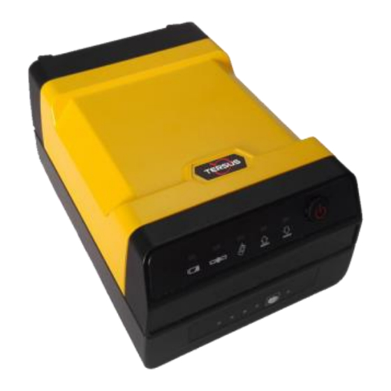
Page 14: Keypad And Display
High-power signals from a nearby radio or radar transmitter may devastate the receiver circuits. Avoid locating the receiver or antenna within 400 meters of powerful radar, transmitters or GNSS antennas. 2.3 Keypad and Display Figure 6 Outlook of front panel Table 3 Description of power LED and button of front panel Icon Name... -
Page 15: Rear Connectors
Table 4 Description of power LED and button of back panel Name Description Icon Connect to the GNSS antenna Common port To connect the external LAN/DC/USB/COM port For the power supply Figure 8 Outlook of Precis-TX204 adapter Figure 9 Outlook of ports on the adaptor 14 / 49... -
Page 16: Table 5 Description Of Ports On The Adaptor
Table 5 Description of ports on the adaptor Icon Interface Description Serial 1/2 RS-232 serial communications using a 9-pin dB9 cable Pass-through to the mainboard without issuing the pass-through command via this port Serial 2/2 RS-232 serial communications using a 9-pin dB9 cable Ethernet Data streaming transmission port Supports link to 10BaseT/100BaseT auto-negotiate networks... -
Page 17: Battery And Power
3 Battery and Power Precis-TX204 uses a built-in rechargeable battery. The operational time provided by the internal battery depends on the type of measurement and operating conditions. Typically, the internal battery provides up to 12 hours operation. External Power Precis-TX204 can use an external power source for power supply. -
Page 18: Set Up Precis-Tx204 Gnss Receiver
Pressing the power button more than 5 seconds, the Precis-TX204 will power on, and the LEDs in the front panel will be on. Pressing the power button more than 5 seconds, the Precis-TX204 will power off, and the LEDs in the front panel will be off. Guidelines for Setting up the Receiver When you set up the receiver, it is better to follow guidelines mentioned below. -
Page 19: Lighting And Surge Protection
4.2.3 Lighting and Surge Protection Tersus GNSS recommends that you install lightning protection equipment at permanent sites. All connections to the receiver should have surge protection. Placing the Antenna Pay attention to below conditions when mounting antenna. Keep the distance from the objects that may cause the multipath effects (such as buildings, trees, reflective surface) for at least 200 m. -
Page 20: System Installation
Connect one end of the RS232-USB adapter to COM1 of Precis-TX204 and the other end to the computer’s USB port. Connect the network cable to the RJ45 jack of Precis-TX204 to link it with network. Connect the power adapter to TX-204 and the mains supply, respectively. -
Page 21: Configure The Receiver
Access Precis-TX204 via Wi-Fi After power on, the Precis-TX204 working as an AP, you can access it with a smart phone or a tablet. Search the Precis-TX204 in the Wi-Fi list, the default SSID of Precis-TX204 is like LSE-TX316C-xxxxxxx, which can be changed, please see 5.3.7.2. -
Page 22: Figure 15 Login To Configuration
The web browser prompts you to enter a username and password as below. Figure 15 Login to configuration The default login account for the receiver as below. • Login Account: admin • Password: password Note: Click remember me option, and then the browser will remember the Login Account and Password you entered for the next time you enter this login screen. -
Page 23: Changing The Setting
Changing the Setting The web interface shows the configuration menus on the left of the browser window, and the setting on the right. Each configuration menu contains the related submenus to configure the receiver and monitor receiver performance. This section describes each configuration menu. -
Page 24: Activity
Figure 19 Position page 5.3.1.2 Activity Lists several important items to help you understand how the receiver is being used and its current operating condition. Items include the identities of currently tracked satellites, internal and external storage usage rate, how long the receiver has been operational, state of the internal battery, power source state, files being logged, and data streams being output. -
Page 25: Google Map
5.3.1.3 Google Map Tap this submenu to show the location of the receiver on Google map. 5.3.2 Satellites Menu Use the Satellites menu to view satellite tracking details and enable/disable GPS, GLONASS or BDS constellations. These menus include tabular and graphical displays to provide all required information on satellite tracking status. -
Page 26: Satellite Tracking Graph
5.3.2.2 Satellite Tracking Graph The following figure is an example of satellite tracking graph page. Figure 23 Satellite tracking Graph 5.3.2.3 Tracking Skyplot The following figure is an example of Tracking Skyplot page. Figure 24 Skyplot 25 / 49... -
Page 27: Satellite Activation
5.3.2.4 Satellite Activation In this submenu, users can enable/disable GPS/GLONASS/BDS/GALIGEO/SBAS system. Figure 25 Satellite activity page 5.3.3 Receiver Configuration Menu Use this menu to configure settings such as the antenna type and height, elevation mask and PDOP setting, the station coordinates, receiver resetting and web interface language. -
Page 28: Receiver Summary
5.3.3.1 Receiver Summary This submenu shows the receiver information and reference station information, including antenna related information, elevation mask angle, station work mode and position, etc. Figure 27 Receiver Summary page 5.3.3.2 Antenna Configuration Use this screen to configure all of the items relating to the GNSS antenna. You must enter the correct values for all antenna-related fields, as the choices you make significantly affect the accuracy for logged data and broadcast RTK correctors. -
Page 29: Figure 29 Station Settings Page
Figure 29 Station settings page For station mode There are three available options: Auto Rover, Auto Base and Manual Base. Auto Rover: The receiver will serve as Rover after the restart. Auto Base: The receiver will serve as Base after the restart, and then broadcast RTK correctors based on coordinates obtained through single-point positioning automatically. -
Page 30: Receiver Reset
Figure 30 Coordinates input Acquire Current Position: Click this button to acquire current position obtained through single-point positioning automatically. Manual Input: Manually input a known coordinates. From CORS: After logging in CORS, the receiver will obtain a coordinates based on fix solution. -
Page 31: Languages
Figure 31 Receiver reset page 5.3.3.5 Languages Use this screen to select the web interface language. Figure 32 Language page 5.3.3.6 User Management Use this menu to config the login info. Figure 33 User management 30 / 49... -
Page 32: Hcppp Settings
5.3.3.7 HCPPP Settings This sub-menu is used to config the data collections for post-processing, please contact Tersus support (support@tersuss-gnss.com) for more about post-processing software. 5.3.4 Data Recording Menu Use the Data Recording menu to set up the receiver to log static GNSS data and to view the logging settings. -
Page 33: Figure 35 Log Settings Page
Figure 35 Log settings page To open or close all the storage threads, click the [ON] or [OFF] button to the right of Log Status field. Note: The [ON] and [OFF] button to the right of Log Status field are the Master Log Switch. -
Page 34: Ftp Push Settings
In this screen, you can set all data logging parameters, and determine whether the recording files will be affected by the FTP Push. The parameters are mainly as follows. • On or Off: Select [Yes] or [No] to determine whether to log data when the Master Log Switch is ON. -
Page 35: Ftp Push Recording
Figure 37 FTP push page 5.3.4.3 FTP Push Recording Shows the related information about the recorded filed that be pushed. And users can click [Clear Ftp Send Log] button in the upper right corner to clear the status of FTP Push operations. -
Page 36: I/O Settings Menu
Figure 39 Data download page Click the directory named as repo to view and download the files currently stored on the receiver. Figure 40 FTP directory page To find the file need to be downloaded, click the name of storage thread. Figure 41 FTP directory page ... -
Page 37: I/O Settings
5.3.5.1 I/O Settings The following figure shows an example of the screen that appears when you select this submenu. Figure 42 I/O settings menu In this submenu, users can configure 5 types of input and output settings. 1) RTK client After configuring the settings of RTK client, users can log on CORS or APIS. -
Page 38: Figure 44 Apis_Base Setting Page
Figure 44 APIS_BASE setting page 2) TCP/UDP client Click the [Connect] button to the right of required TCP/UDP Client. The IO Settings screen will appear. Select the connection protocol from the drop-down list. Enter the IP and Port of the target server. Configure messages that you want to output to the target server. -
Page 39: Figure 46 Ntrip Server Setting Page
Figure 46 NTRIP server setting page Connection protocol: TCP Figure 47 TCP server setting page 4) BlueTooth Click the [Settings] button to the right of BlueTooth. The BlueTooth Set screen will appear. Configure the messages that you want to transmit through BlueTooth. Click [Confirm] button to save the settings and start to transmit. -
Page 40: Network Set Menu
Figure 48 BlueTooth port setting page 5) GSM Click the [Settings] button at the right of GSM. The Reference Station Config screen will appear. This page has the same function as Receiver->Reference Station Settings page. Please see 5.3.3.3 for detail. 5.3.6 Network Set Menu Use this menu to check and configure the Ethernet settings, seven submenus are included in this menu. -
Page 41: Wired Network Setting
Figure 50 Network information 5.3.6.2 Wired Network Setting Use this submenu to configure the related parameters of the Network, including static IP, subnet mask, etc. Figure 51 Network setting page 5.3.6.3 Mobile Network Setting Use this menu to check and configure the Wi-Fi settings. It’s recommended that GPRS model status is set to ON and Auto Start Yes, all other options can be used default values. -
Page 42: Other Submenus
Figure 52 Network Set page 5.3.6.4 Other Submenus It’s recommended that all the options in the left four submenus (Email Alarm, HTTP, HTTPS and FTP Service) are not changed. 5.3.7 Module Setting Menu Use this menu to configure the Wi-Fi settings; three submenus are included in it. Figure 53 Module Setting 5.3.7.1 Summary The following figure shows an example of the screen that appears when you select... -
Page 43: Wi-Fi Settings
Figure 54 Summary page 5.3.7.2 Wi-Fi Settings Use this menu to configure the receiver’s Wi-Fi setting. Figure 55 Wi-Fi Setting page 5.3.7.3 BlueTooth set Figure 56 BlueTooth Set page 42 / 49... -
Page 44: Firmware Menu
5.3.8 Firmware Menu Use this menu to check the current firmware information, download the system log, update the receiver firmware, download or update the configuration file and register the receiver. Figure 57 Submenus in Firmware 5.3.8.1 Board Upgrade Press Confirm in this page to select the FW you want to replace the current one in the receiver. -
Page 45: System Log
Figure 59 Firmware information 5.3.8.3 System Log Use this submenu to download the system log of the receiver. Figure 60 System log download page 5.3.8.4 Firmware Update Use this submenu to load new firmware to the mother board. Click the [Browse] button to locate the upgrade file. -
Page 46: Gnss Registration
[Confirm] button to confirm the selected file and start updating. Figure 62 Config file setting page 5.3.8.6 GNSS Registration Use this submenu to register the receiver. Paste or enter the registration code to the Registration Code field. Click [Registration] button to complete the registration. Figure 63 GNSS registration page 5.3.8.7 The Hardware Version Figure 64 Hardware Version page... -
Page 47: Upgrade Online
5.3.8.8 Upgrade Online Figure 65 Upgrade Online page 5.3.8.9 User log Figure 66 User log page 46 / 49... -
Page 48: Appendix
6 Appendix RTK configuration A RTK positioning system example is given below to show the detailed steps: Base config: FIX POSITION lat lon hgt ECUTOFF BD2 10.0 ECUTOFF GPS 10.0 ECUTOFF GLONASS 10.0 INTERFACEMODE COM2 NONE RTCMV3 ON LOG COM2 RTCM1074 ONTIME 1 LOG COM2 RTCM1084 ONTIME 1 LOG COM2 RTCM1124 ONTIME 1 LOG COM2 RTCM1005 ONTIME 10... -
Page 49: Troubleshooting
SAVECONFIG Troubleshooting Use this appendix to identify and solve common problems that may occur during the use of the receiver. Please read this section before you contact Tersus GNSS Technical Support. Table 6 Description of receiver issues Issue Possible Cause... - Page 50 All Information in this document is subject to change without notice and does not reflect the commitment on Tersus GNSS. No part of this manual may be reproduced or transmitted by all means without authorization of Tersus GNSS. The software described in this document must be used in terms of the agreement.
Need help?
Do you have a question about the PRECIS-TX204 and is the answer not in the manual?
Questions and answers