
Related Manuals for Canon QY8-1360-000


Summary of Contents for Canon QY8-1360-000
- Page 1 REVISION 0 QY8-1360-000 OCT. 1998 COPYRIGHT 1998 CANON INC. CANON BJC-7100 1098 AB 5.00-0 PRINTED IN JAPAN (IMPRIME AU JAPON)
- Page 2 1098 AB 5.00-0...
- Page 4 This manual may include technical inaccuracies or typographical errors due to improvements or changes in the products. When amendments are made to the content of this manual, Canon will issue technical information as the need arises. In the event of major alterations to the content of this manual over a long or short period, Canon will publish a revised version of the manual.
-
Page 5: About This Manual
This part explains maintenance of the unit. It includes details of disassembly/assembly, adjustments required when assembling, troubleshooting procedures, and wiring/circuit diagrams, etc. This manual does not contain complete information required for disassembling and assembling the BJC-5500 printer. Please also refer to the separate Parts Catalog. -
Page 6: Table Of Contents
2.1.1 Unpacking the BJ cartridge 1 - 7 2.1.2 BJ cartridge protection 1 - 8 2.1.3 Power on/off 1 - 8 2.1.4 When not using the printer 1 - 9 2.1.5 Ink electroconductivity 1 - 9 2.2 Ink Tank Handling 1 - 9 2.2.1 Unpacking the ink tank... - Page 7 3 - 6 1.3.4 Replacing the ink tanks 3 - 7 1.3.5 Cartridge container [SB-60] 3 - 8 1.4 Turning Printer Power On and Off 3 - 8 1.4.1 Turning the power on 3 - 8 1.4.2 Turning the power off 3 - 9 1.5 Loading Printer Paper...
- Page 8 2.5 Head Overheat Protection 4 -13 3. PRINTER'S MECHANICAL SYSTEM 4 -13 3.1 Overview 4 -14 3.1.1 Structure of printer's mechanical system 4 -15 3.2 BJ Cartridge 4 -15 3.2.1 BJ Cartridge structure 4 -19 3.2.2 Structure of BJ head unit 4 -21 3.2.3 Nozzle arrays...
- Page 9 Page 5 - 2 2.1 List of Tools 5 - 3 3. APPLYING GREASE 5 - 4 4. DISASSEMBLY AND REASSEMBLY 5 - 4 4.1 Disassembly and Reassembly 5 - 4 4.2 Notes on Disassembly and Reassembly 5 - 4 4.2.1 Main cover 5 - 4 4.2.2 Carriage unit...
-
Page 10: Illustration Index
Figure 3 -15 3 -13 Figure 3 -16 3 -14 Figure 3 -17 3 -17 Figure 3 -18 The Printer's Moving Parts Front Cover Ink Path BC-62e Photo and BC-61 Ink Mist AC Adapter BJ Cartridge Metal Plate Removing the BJ Cartridge Cap and Tape... - Page 11 3 -23 Figure 3 -22 EEPROM Data Print (Sample) Part 4: TECHNICAL REFERENCE 4 - 1 Figure 4 - 1 Printer Block Diagram 4 - 2 Figure 4 - 2 Flowchart of Initialization Sequence 4 - 3 Figure 4 - 3...
- Page 12 Page 5 -10 Figure 5 -12 Thickness Gauge Setting 5 -10 Figure 5 -13 Check the Head Gap 5 -11 Figure 5 -14 Adjust the Head Gap 1 5 -12 Figure 5 -15 Adjust the Head Gap 2 5 -37 Figure 5 -16 Logic Board 5 -39...
- Page 13 BJ Cartridge vs Print Mode Paper Specifications IO Signals Compatible Mode IO Signals in Nibble Mode IO Signals in ECP Mode Printer Paper Settings Operator Calls Service Calls Service Mode Number of Passes vs Number of Operational Head Nozzles Main Default Print Mode Settings...
-
Page 15: Part 1: Safety And Precautions
2.3 Printer Handling 1 -12 3. NOTES ON SERVICING 1 -12 3.1 EEPROM Data 1 -13 3.2 Service Mode of Printer Driver 1 -13 3.3 Protecting the Power Supply 1 -14 3.4 Static Electricity 1 -15 3.5 Disassembly and Assembly 1 -15 3.6 Self-Diagnosis... -
Page 17: Safety Precautions
1. SAFETY PRECAUTIONS 1.1 Moving Parts Be careful not to let your fingers, hair, clothing, accessories, etc., become caught up in the moving parts of the printer. There are moving parts associated with the carriage motor and paper feed motor. Carriage motor... -
Page 18: Front Cover
Part 1: Safety and Precautions BJC-7100 1.2 Front Cover Hold the front part of the front cover to open and close the cover. Be careful not to pinch your fingers between the front and main cover when closing the front cover. Figure 1-2 Front Cover... -
Page 19: Ink Stains
1.3 Ink Stains 1.3.1 Ink path Be careful not to touch the ink path as it may stain your hands, clothes, printer, work table etc., during servicing. The ink path consists of the BJ cartridge nozzles, head cap, waste ink tube, head wiper, cleaner unit, maintenance jet receiving section, and waste ink absorber. -
Page 20: Ink Mist
1.3.2 Ink mist The BJ cartridge ejects ink onto the paper. After prolonged or heavy-duty use of the printer, a small amount of ink mist splattered during printing can dirty the printer such as the platen. Turn off the power, open the front cover, and clean the dirty parts with a soft moist cloth. -
Page 21: Live Parts
1.4 Live Parts When the plug of the printer's AC adapter is plugged into a live power outlet, the power supply unit of the printer is live regardless of the power being set to ON or OFF using the POWER button. -
Page 22: Bj Cartridge Metal Plate
CAUTION Danger! High Temperature! Do not touch. The printer has the following protective mechanisms to detect overheating: 1. Overheat detection when replacing cartridge If overheating is detected, a beeper sounds four times and the carriage does not return to the replacement position. This is to prevent the user from touching the BJ cartridge's metal plate. -
Page 23: Machine Precautions
BJ cartridge, promptly install the cartridge in the printer or store it in the cartridge holder. If the BJ cartridge is not capped or stored in the cartridge holder, the nozzles may clog due to dried out ink or dust, etc. -
Page 24: Power On/Off
2.1.4 When not using the printer Keep the BC-60 BJ cartridge installed in the printer even when the printer is not in use. The BC-62e Photo and BC-61 BJ cartridges can be left installed in the printer or stored in the cartridge holder. -
Page 25: Ink Electroconductivity
The ink used in the BJ cartridge can conduct electricity. If any ink leaks into the printer's mechanical parts, use paper towels, etc., to wipe clean. If the ink leaks onto the printer's electrical components, use tissue paper, etc., to wipe clean. If the ink gets to the IC chips on the PCB, or if it is too difficult to thoroughly clean off the ink, replace the respective parts. -
Page 26: Printer Handling
Part 1: Safety and Precautions 2.3 Printer Handling 2.3.1 Spurs Take care not to bend the tips of the spurs. The spurs that transport and eject the paper after printing are very small and can easily be deformed. If a spur is deformed, its contacting surface with the printed paper increases, creating a dotted line. -
Page 27: Ink Leakage And Dry-Out
"Part 3: 2.2 Manual Capping" (page 3-13). 2.3.4 Carrying the printer Hold both sides of the bottom of the printer to carry it. Note that inserting your hand into the paper outlet may dislodge or damage the paper guides. Figure 1-14 Capping Position... -
Page 28: Notes On Servicing
If you want to check the stored data, be sure to make a test print before resetting the EEPROM. Note that you cannot reenter the data from the printer's control panel or by using a computer. -
Page 29: Service Mode Of Printer Driver
See "Part 3: 3.3.2 Service mode of printer driver" (page 3-18) for details. 3.3 Protecting the Power Supply The power supply for the BJC-7100 printer consists of an AC adapter and a power supply circuit on the logic board. Provided the AC supply is connected, the printer power supply is live whether or not the power is set ON or OFF using the POWER button. -
Page 30: Static Electricity
The electrostatic charge accumulated in clothing can damage electrical components and alter their electrical characteristics. Before disassembling the printer to service it, use a wriststrap or other grounded metal object to discharge the static electricity. The following parts must not be touched before you have discharged the static electricity from your body: •... -
Page 31: Disassembly And Assembly
In addition, do not attempt to disassemble the AC adapter, BJ cartridge, or ink tanks. In principle, do not loosen any of the screws painted red in the printer mechanism (except when adjusting the head gap using the jig). The red screws hold the adjustable plate that determines the gap between the nozzles of the BJ cartridge and the platen. - Page 32 Part 1: Safety and Precautions BJC-7100 This page intentionally left blank 1-16...
-
Page 33: Part 2: Product Specifications
Part 2 PRODUCT SPECIFICATIONS Page 2 - 1 1. PRODUCT OUTLINE 2 - 1 1.1 Outline 2 - 2 1.2 Features 2 - 3 1.3 BJ Cartridge 2 - 6 1.4 SB-60 BJ Cartridge Container 2 - 6 1.5 Consumables 2 - 7 2. -
Page 35: Product Outline
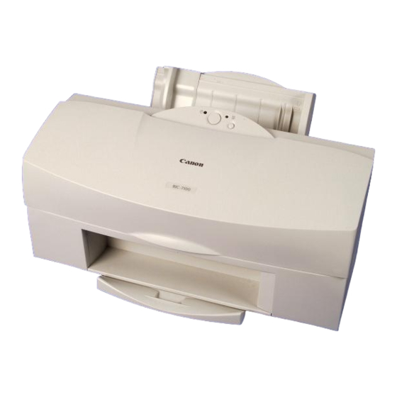
1. PRODUCT OUTLINE 1.1 Outline The BJC-7100 is a personal desktop color bubble-jet printer that uses a new 600dpi BJ cartridge and technology to achieve outstanding print quality and photographic realism. The printing process uses an ink optimizer to enable water resistance printing on plain paper. -
Page 36: Features
This interface is compatible with nibble mode and ECP mode. 8. The built-in control mode is the Canon extended mode. The host computer sends print signals in Canon extended mode, generated by the special printer driver. 9. The printer is supplied with Windows 3.1, Windows 95 and Windows 98 special printer driver. -
Page 37: Bj Cartridge
BJC-7100 1.3 BJ Cartridge 1.3.1 Black BJ cartridge (BC-60) The BC-60 BJ cartridge is used for monochrome printing and for printing using the ink optimizer. It is a head and ink tank integrated type, disposable BJ cartridge consisting of a unified BJ head and ink tanks for black ink and ink optimizer. There are two parallel BJ heads, each with 304 nozzles. -
Page 38: Photo Bj Cartridge (Bc-62E Photo)
Part 2: Product Specifications 1.3.2 Photo BJ cartridge (BC-62e Photo) The BJ head for the BC-62e Photo has been modified to considerably improve the ink jet emission precision. The BC-62e Photo BJ cartridge is used for photo-realism (super photo mode) (when printing photographs with substantial numbers of half-tones and light colors). -
Page 39: Color Bj Cartridge (Bc-61)
BJC-7100 1.3.3 Color BJ cartridge (BC-61) The BC-61 BJ cartridge is used for color printing (denser colors and filling larger areas with color). The cartridge consists of a main unit that separates the BJ heads, and disposable ink tanks (BCI-61 Color). The BJ head has 240 nozzles supplying the color inks. -
Page 40: Sb-60 Bj Cartridge Container
Except for the packaging, these consumables are identical to the BJ cartridges supplied with the new printer. The BC-62 Photo used in the BJC-700J Printer cannot be used on this printer. If the BC-62 Photo is installed on BJC-7100, printing is carried out, however, print quality may deteriorate drastically. -
Page 41: Specifications
Select either of Unidirectional or BIdirectional as the printing mode. (See "Part 4: 2.2 Print Mode" (page 4-8) ) 8. Bit image printing Data matrix: Canon extended mode: Raster image format Resolution: Canon extended mode: 300, 600, and 1200dpi 9. Buffer 256KB 10. -
Page 42: High-Resolution Paper
Glossy photo paper: High-gloss photo film: 1 Fabric sheets: T-shirts transfer 15. Paper sizes Cut sheets: Envelopes: Recommended plain paper: Canon bubble jet paper High-resolution paper: Glossy photo paper: High-gloss photo film: Glossy photo card: Transparencies: Back print film: Fabric sheets: T-shirts transfer: 16. - Page 43 BJC-7100 Color BJ cartridge BC-61 Nozzles: One row of 80 nozzles Ink colors: Yellow, magenta, and cyan Service life: Approx. 275 pages per tank (when printing standard color pattern at 7.5% duty per color) Head service life: Approx. 2000 pages (when printing standard color pattern at 7.5% duty per color) 17.
-
Page 44: Paper Specifications
Other Paper T-Shirts transfer TR-201 *1: A4+ size paper is a Canon original size paper that, measuring 222.7 slightly larger than A4 size paper. The A4+size paper allows you to print to the full A4 size. The LTR+ size, measuring 228.6 full LTR size. -
Page 45: Printing Range
BJC-7100 2.2.2 Printing range A4, A5 and B5 Sizes 7.0mm 3.4mm 3.4mm A4+and Letter (LTR+) Sizes 5.1mm A4+ 5.9mm Letter+ 5.1mm : Recommended Printing Area : Printable Area (1) Monochrome Printing (2) Color or Photo Printing Letter (LTR) and Legal (LGL) Sizes (1) 12.0mm (2) 21.0mm (1) 22.6mm... -
Page 46: Interface Specifications
Material: AWG No. 28 or thicker (American Wire Gauge) Type: Shielded twisted pair cable Length: 2.0m max. 5) Interface connectors Printer: Amphenol 36-pin 57-40360 or equivalent Cable: Amphenol 36-pin 57-30360 or equivalent 6) IO signals and pin configuration TABLE 2-3 IO SIGNALS IN COMPATIBLE MODE Pin No. - Page 47 BJC-7100 TABLE 2-4 IO SIGNALS IN NIBBLE MODE Pin No. Signal Symbol on Circuit Diagram HostClk [STROBE] Data 1 [DATA 1] Data 2 [DATA 2] Data 3 [DATA 3] Data 4 [DATA 4] Data 5 [DATA 5] Data 6 [DATA 6] Data 7 [DATA 7] Data 8...
- Page 48 When this signal is High, the printer is BUSY; when Low, the printer is READY. The printer receives data at least 1 Byte when Data Stobe signal is input in the case Busy signal goes to "H" regardless of receiving data.
- Page 49 BJC-7100 Init [Input] When it changes to Low, this signal sets the printer in the BUSY state, then resets the printer by changing from Low to High. The pules width of this signal is requiired longer than 5 micro seconds.
- Page 50 BJC-7100 Host Busy [Input] Indicates that the host is ready to receive the data from the printer by making the Host Busy signal Low in the reverse data transmission phase. After that, it goes High when data is received from the printer to verify receiving data.
- Page 51 BJC-7100 Ack Reverse [Output] This signal remains High when data is sent from the host computer to the printer. It remains Low in the reverse data transmission phase. When switching from the forward to reverse data transmission phase, this signal...
- Page 52 0.5 s Min. Min. Min. Min.0.8 s 4 s (When HS mode is invalid) Figure 2-8 Compatible Mode Bit2 0000 0000 Invalid Printer Busy Bit3 Host Bit0 With data Bit1 Nibble mode Support Figure 2-9 Nibble Mode 0001 0000 Byte0...
-
Page 53: Part 3: Operating Instructions
1.1 Unpacking 3 - 2 1.2 Installation Location 3 - 3 1.3 Installation 3 - 8 1.4 Turning Printer Power On and Off 3 - 9 1.5 Loading Printer Paper 3 -10 1.6 Names of Parts and Their Functions 3 -12 2. -
Page 55: Printer Setup
Part 3: Operating Instructions BJC-7100 1. PRINTER SETUP 1.1 Unpacking After unpacking, make sure the items below have been included: Instruction Manual Instructions/ Driver Software BJ Cartridge BJ Cartridge Container Packing Packing Packing Packing Carton Packing Packing Tapes Tapes Tapes... -
Page 56: Installation Location
1.2 Installation Location To ensure optimum performance, install the printer where there is adequate space. It is also important that you install the printer where the vibration caused by the carriage movements will not cause problems. The figure illustrates the printer dimensions. -
Page 57: Installation
2) Press the printer POWER button. The printer beeper sounds and the power lamp blinks. 3) After the printer has initialized itself, the carriage moves to the left for the BJ cartridge to be installed. 1. Connect the power cord to the AC adaptor. -
Page 58: Installing The Bj Cartridge
2) Installing the BJ cartridge Open the printer’s front cover and install the BJ cartridge on the carriage. Install the BC-60 on the left holder and the BC-62e Photo (or BC-61) on the right holder. - Page 59 BJC-7100 3) Aligning the print heads Because two BJ cartridges are installed in the printer, differences in how they are secured and in the cartridges themselves can shift the way ink is ejected onto the paper. To even out any differences and ensure satisfactory print quality, follow the procedure below for adjusting the relative positions of the print heads after completing the setup procedure on the PC.
-
Page 60: Replacing The Ink Tanks
2) Removing an ink tank Press the REPLACE button to move the carriage to the cartridge replacement position (you can also use the printer driver). As shown in Figure 3-8, lift the front of the ink tank to remove the ink tank from the holder. -
Page 61: Cartridge Container [Sb-60]
BJC-7100 1.3.5 Cartridge container [SB-60] The printer is supplied with a container for storing the BC-61 or BC-62e Photo BJ cartridges for users who are using both the BC-61 and BC-62e Photo. (Note that the BC-60 cannot be stored in the container.) When the BC-61 is installed in the printer, the BC-62e Photo is stored in the container, and vice versa. -
Page 62: Turning Printer Power On And Off
1.4 Turning Printer Power On and Off 1.4.1 Turning the power on When the printer is connected to a power supply, press the POWER button to turn it ON. The beeper sounds once and the printer initializes itself. If no BJ cartridge has been installed, the POWER indicator blinks to show that the printer is waiting for the cartridge to be installed. -
Page 63: Loading Printer Paper
To obtain optimum print quality, either use the auto sheet feeder or the manual feed on the back of the printer, depending on the type of print paper you are using. Because this printer automatically adjusts the platen-head gap according to the paper being used, there are no paper selection or head gap levers. -
Page 64: Names Of Parts And Their Functions
Part 3: Operating Instructions 1.6 Names of Parts and Their Functions The different parts of the printer and their functions are shown below. FRONT Paper Rest Supprots the stack of paper loaded in the sheet feeder. Sheet Feeder Print paper is loaded in the sheet feeder. - Page 65 This ensures that the paper is fed correctly. AC Adaptor and Power Cable Once installed on the printer, the user does not need to remove the AC adaptor when disconnecting the power cord. Plug the power cable into a wall outlet.
-
Page 66: Transporting The Printer
4) Open the front cover and check that the carriage is locked in the capping position (right side of printer). If a fault has occurred and the carriage is not in the capping position, move it manually to the capping position. (See below: Operations performed... -
Page 67: Manual Capping
BJC-7100 2.2 Manual Capping The BJ cartridges of the BJC-7100 printer can be capped manually only by service personal. 1) Insert a tweezers into the hole for manual capping positioning and rotate the gears slowly counterclockwise. 2) When the cap and carriage lock lever are in the lowest position, slowly move the carriage to the capping position. -
Page 68: Printer Servicing Functions
BJ Cartridge Overheat Error *1: A waste ink error (service call) will occur if you continue to use the printer. When using a bidirectional parallel interface (Nibble or ECP Modes), a description of the error is displayed on the host computer’s screen. -
Page 69: Service Calls
In the case of service calls, "service personnel call error messages" are displayed on the host computer’s screen via the printer driver, and you can check the details of the error as shown in the table below by the number of times that the beeper on the main unit sounds. -
Page 70: Warning Indications
Printing is not forcibly stopped while warnings are displayed. BJ cartridge mismatch warning If you select the photo ink system using the printer driver controls and start printing with a color BJ cartridge [BC-61] installed, the printer functions as described below. -
Page 71: Function Settings
BJC-7100 3.3 Function Settings This printer has no function selector for setting functions. Use the Windows driver to make the respective settings. For details, see the Windows Driver Guide included with the printer. 3.3.1 Items set by control function Procedure 1) Open the printer driver control dialog box. -
Page 72: Service Mode Of Printer Driver
"OFF": First power-on cleaning performed (default) "ON": First power-on cleaning not performed If the AC power supply is frequently disconnected (such as when the printer is linked to a computer’s power supply), setting economy cleaning ON reduces ink consumption and minimizes the startup time by omitting the first power-on cleaning. -
Page 73: Eeprom
BJC-7100 also allows you to manually clean the heads using the RESUME button. Note, however, that if you perform manual cleaning, the heads of both BJ cartridges installed in the printer are cleaned. (You can clean just one of the heads if you use the printer driver.) -
Page 74: Test Printout
(HR-101). 1) Insert a sheet of cleaning sheet into the printer. 2) With the printer power ON, press the RESUME button until the beeper sounds four times. 3) The POWER indicator blinks. (Any paper in the printer is ejected.) 4) Paper loading and ejecting operations are performed. -
Page 75: Service Mode
1) While holding down the RESUME button, press the POWER button to turn on the printer. 2) Holding down the POWER button, press the RESUME button twice before the printer completes its initialization sequence (while the POWER indicator is blinking). -
Page 76: Final Factory Test Pattern
3) Press the POWER button to reset the total waste ink amount recorded in the EEPROM. 4) After resetting the total waste ink amount, the printer automatically turns off. 2) All service data reset If, when you replace the logic board, you do not intend to continue using the existing EEPROM data, reset all the service data in the EEPROM on the new logic board, and replace the waste ink absorbers and maintenance jet absorbers. -
Page 77: Printing Eeprom Data
Check that "BJC-7100 Vx.xx Vx.xx x" is displayed at the top left of the test pattern. When set to the Japanese function set, "BJ F800 Vx.xx Vx.xx x" is displayed. If the printer has been set for the BJ F800 set, reselect the overseas function set as follows: 1) Enter to a service mode. -
Page 78: Other Function
Part 3: Operating Instructions 3.8.5 Other Function The following functions are provided in addition to the functions described above. These functions are for carrying out special tests, and are not used during normal servicing. They are described here for reference only. 1. -
Page 79: Part 4: Technical Reference
4 -33 3.4 Carriage 4 -36 3.5 Paper Feed/Sheet Feeder Mechanism 4 -39 4. PRINTER ELECTRICAL SYSTEM 4 -39 4.1 Overview of Printer Electrical System 4 -40 4.2 Logic 4 -45 4.3 Electrica System 4 -46 5. DETECTION FUNCTIONS 4 -46 5.1 Sensor-based Detection Functions... -
Page 81: Overview
VH (+20VDC) Controller VM (+27.6VDC) Paper-end Sensor Pickup Roller Sensor Reset Control EEPROM Circuit Buttons Figure 4-1 Printer Block Diagram Part 4: Technical Reference Carriage Motor Purge Unit • Purge Sensor CNPGS CNCR Carriage Motor Driver Indicator Control ROM DRAM... -
Page 82: Initial Flowchart
Part 4: Technical Reference 1.2 Initial Flowchart The following flowchart shows the steps in the initialization sequence that takes place when the power is turned on and before the printer enters the online state. Start Connect power cable of AC adaptor to wall outlet. -
Page 83: Print Signal Sequence
: Control Commands and Signals The BJC-7100 supports the Canon extended (native) mode, but not emulation. The print signals sent from the host PC are therefore Canon extended mode signals converted by the printer driver. Printer Controller Figure 4-3 Print Signal Sequence... -
Page 84: Bj Cartridge Drive
The control signals determine the timing with which ink is ejected from the nozzles in the BJ heads and the amount of ink. These are optimized by the printer controller according to the conditions shown bellow. The control signals also stabilize the amount of ink by keeping the BJ heads at the optimum temperature. -
Page 85: Power-Off Sequence Flowchart
POWER indicator OFF Printer stops. * : If the power is turned off using the POWER button or the printer driver control sheet (soft power off) during cleaning or capping operations, this sequence starts on completion of that operation. Figure 4-4 Power-Off Sequence Flowchart... -
Page 86: Firmware
DATA STROBE falls. After the BUSY signal has been output, the printer controller fetches the latched data via the DRAM bus to the receive buffer in the DRAM. After writing the data to the receive buffer in the DRAM, the printer controller outputs an ACKNLG signal, sets the BUSY signal "Low", and waits... -
Page 87: Nibble Mode
BJC-7100 2.1.2 Nibble mode In nibble mode, 8-bit data is sent from the printer to the host PC in two 4-bit blocks. The printer lowers the DataAvail signal when it is ready to send data to the host PC. After confirming the fall in the HostBusy signal, the printer prepares 8 bits of data and outputs the low 4 bits on the control signal line on the fall in the PtrClk signal. -
Page 88: Print Modes
4+P: 4-pass printing/24 nozzles and 16 nozzles alternately repeated 3. Carriage Speed 24: 24 inch/sec 16: 16 inch/sec 17: 17.5 inch/sec 4. The Black + Color mode is operable even if the photo BJ cartridge is attached on the printer. Standard Standard Quality Draft... -
Page 89: Plain Paper Optimized Printing Mode (P-Pop)
Only when you select plain paper (in other than draft mode) using the printer driver, the BJC-7100 ejects ink optimizer from the BC-60's ink optimizer head. The printer jets the ink optimizer onto the plain paper, followed by the normal ink to minimize smearing and improve the ink's water resistance. -
Page 90: Print Mode Settings
Part 4: Technical Reference 2.2.5 Print mode settings The following table shows the default print mode settings in the printer driver. Select the Print Mode parameters to change the settings. TABLE 4-2 MAIN DEFAULT PRINT MODE SETTINGS Print mode system... -
Page 91: Smoothing Function
2 pass data. 2.4.3 Ink smear prevention Printed pages ejected from the printer dry naturally in the paper output tray. If, before a page has dried, the next printed page is ejected onto it, there is a risk that the ink on the first page will be smeared. -
Page 92: Head Overheat Protection
If the head temperature continues to rise, the printer stops printing; the carriage continues to move and the paper is fed through the printer. The printer then discards any further data sent from the host PC, and performs cleaning operations, ink-out detection, and checks for failure of the head temperature sensor. -
Page 93: Printer's Mechanical System
BJC-7100 3. PRINTER'S MECHANICAL SYSTEM 3.1 Overview This section provides an overview of the printer's mechanical system. Black BJ Cartridge Color/Photo Ink Tank Color/Photo BJ Cartridge Page Output Guide and Tray Figure 4-12 Printer's Mechanical System Part 4: Technical Reference... -
Page 94: Structure Of Printer's Mechanical System
6) Manual Feed Slot Paper can be fed into the printer manually from the manual feed slot on the back. Paper fed manually into the printer takes precedence over any print paper already in the sheet feeder. -
Page 95: Bj Cartridge
BJC-7100 3.2 BJ Cartridge 3.2.1 BJ cartridge structure 1) BC-60 In the BC-60, the BJ head is unified with the ink tank. Head Clip Cartridge body The cartridge body houses the ink sponges and is the base for the BJ head unit. Ink sponges The two ink sponges hold the ink and ink optimizer that are fed to the BJ head unit. - Page 96 Part 4: Technical Reference BJ head unit The BJ head unit receives the ink from the ink pipes and ejects the ink at the print media according to the print signals from the signal contacts. Head clip/Screws The BJ head unit is fastened to the cartridge body using head clip and screws. Head packing The head packing ensures that the ink pipes and BJ head unit are in close contact to prevent ink leaking.
- Page 97 BJC-7100 BC-62e Photo Tank Label Tank Cover Ink Sponges Cyan Magenta Yellow Photo Cyan Photo Magenta Photo Yellow Ink Supply Pieces Tank Body Figure 4-15 Structure of BC-62e Photo Tank body The tank body houses the ink sponges. Ink sponges The ink sponges hold the inks that are fed to the BJ head unit.
- Page 98 Part 4: Technical Reference BJC-7100 Air paths/Tank label Air vents or paths are created between the inside and outside of the BJ cartridge through the holes and grooves in the cover and the label that is applied to it. The air vents prevent pressure fluctuations inside the BJ cartridge due to ink consumption and atmospheric conditions, and help stabilize the supply of inks to the print head.
-
Page 99: Structure Of Bj Head Unit
BJC-7100 3.2.2 Structure of BJ head unit The structure of the BJ head unit is different for each type of BJ cartridge. 1) BC-60 The BC-60 has two identical print heads, each with 310 nozzles, mounted side by side. One head ejects black ink, while the other ejects the ink optimizer. Aluminum Plate Heater Board Flexible Cable... - Page 100 The signal contacts are connected to the heater board by printed pattern wiring. The contacts are in contact with the signal contacts on the carriage, and are used for the input and output of print signals and sensor signals between the printer and BJ print head (heater board).
-
Page 101: Nozzle Arrays
BJC-7100 3.2.3 Nozzle arrays In each of the BJ print heads, the nozzles are arranged in vertical rows at a pitch of 1/600-in. Ink optimizer nozzle Print direction forword (Direction in which carriage travels) In addition to the nozzles shown in Figure 4-19, all BJ print heads have dummy nozzles at the top and bottom edges. -
Page 102: Signal Contacts
The signal contacts on the flexible cable are in contact with the signal contacts on the carriage, and are used to input and output print signals and sensor signals between the printer and BJ print head (heater board). BC-60 2 N.C. - Page 103 BJC-7100 Pin No. BJ print head 19-21 *: Symbols in the BJ print head columns are as follows: ALL: Signals input to all heads OM: IO signals for ink optimizer head only BK: IO signals for black head only PH: IO signals for photo head only CL: IO signals for color head only Signal IN/OUT...
-
Page 104: Drive Circuit
Part 4: Technical Reference 3.2.5 Drive circuit The drive circuit built into the heater board controls the ejection of inks. The drive circuit differs according to the type of BJ cartridge. 1) BC-60 The black head and ink optimizer head are each equipped with the drive circuit shown in Figure 4-21. - Page 105 BJC-7100 2) BC-61 and BC-62e Photo The color head and photo head are equipped with the drive circuit shown in Figure 4-22. RANK Rank Resistance SUBH Sub-heater HEATE ODDE EVENE 240-bit IDATA Shift Register DCLK LTRST LTCLK VDDH VDDH See diagrams below. Head Temperature Sensor Color Head Contact...
- Page 106 Differences in the heater characteristics of the various BJ heads are ranked and marked using their resistance, which is detected by the printer. The resistance is read by the A/D board of the MPU as a voltage and converted to digital format to detect the rank, allowing the BJ print heads to be controlled for optimum print quality.
- Page 107 BJC-7100 TABLE 4-4 AND GATE CONTACTS AND IDATA ORDER Ink optimizer head VDDH (High) BLOCK6 1 Output sequence of BLOCK1 to 6 BLOCK1 1–7 BLOCK2 8–25 BLOCK3 26–43 138–155 BLOCK4 44–61 156–173 BLOCK5 62–79 174–191 80–99 192–211 BLOCK6 Order of IDATA* Reverse order 2, 4, 6–310 ODDE*...
-
Page 108: Bj Cartridge Detection
Photo printing *1: ID1 of the ink optimizer head is not detected by the printer. *2: The operator uses the printer driver to select whether printing is continued using only the color ink system, or whether printing is interrupted. TABLE 4-6 INDEX CONNECTIONS... -
Page 109: Purge Unit
When the cap is open and the printer is idle (waiting for data), the maintenance jets are operated at 15 second intervals if paper is being fed. If no data is received for 120 seconds, the nozzles are capped. -
Page 110: Structure Of Purge Unit
*2: Standard manual cleaning. *3: Deep cleaning. *4: Excluding when BJ cartridge installed and capped in the printer. *5: Executed only when printing is performed after turning on the printer. 3.3.2 Structure of purge unit 1) Purge drive gear The purge drive gear is driven via the transmission arm gear by the feed roller, which is, in turn, driven by the paper feed motor. - Page 111 3) Caps The purge unit of the BJC-7100 printer has four caps: two for ink purging and capping, and two for capping only. After the carriage moves to the capping position, the caps are pressed against the print head faces.
- Page 112 Part 4: Technical Reference Waste Ink Tube Ink: Lower Tube Ink Optimizer: Upper Tube Purge Drive Gear Pump Section (For Purging and Capping) Purge Unit Carriage Lock Lever Slide Lock Lever Wiper Figure 4-23 Purge Unit 4-32 BJC-7100 (For Capping)
-
Page 113: Carriage
When the carriage moves left, the side of the ink optimizer head presses against the wiper lever on the left of the printer to set the wiper. When the carriage then moves right, the hook on the bottom of the carriage pulls the latch lever so that the ink optimizer head wiper wipes the face of the ink optimizer head. -
Page 114: Carriage Structure
Except when the carriage is at the right edge of the printer, the slide lock lever of the purge unit locks the operation of the transmission arm. - Page 115 BJC-7100 Sheet Feeder Gear Driving Sheet Feeder Sheet Feeder Drive Gear Transmission Arm Gear Sheet Feeder Unit Feeding Paper Sheet Feeder Unit Driving Purge Unit 1) Wiping/Capping Release 2) Purge/Dummy Purge Figure 4-25 Paper Feed Motor Drive Switching Part 4: Technical Reference Slide Lock Lever Top View Transmission Arm...
-
Page 116: Paper Feed/Sheet Feeder Mechanism
On completion of printing, the page is ejected by the paper output roller. 2) Auto platen-head gap adjustment function The BJC-7100 printer can print without switching the carriage position according to the thickness of the media being printed on. The paper feed roller is pressed up by coil springs toward the pressure roller while the paper output roller is also pressed up by coil springs toward the spurs. -
Page 117: Auto Sheet Feeder (Asf)
BJC-7100 Auto Sheet Feeder (ASF) BJ Cartridge Paper Output Unit Spurs Manual Feed Paper Output Rollers Pickup Roller Sensor Pickup Roller Pressure Roller Sensor Flag Paper Feed Roller Pickup Guide Figure 4-27 Paper Feed Mechanism 4-37 Part 4: Technical Reference Print Media Paper End Sensor... -
Page 118: Paper Feed/Sheet Feeder Mechanism Structure
BJC-7100 3.5.2 Paper feed/sheet feeder mechanism structure The sheet feeder of the BJC-7100 printer has no mechanical paper selection lever. Provided the print media is within the specifications, the media is fed without having to adjust the carriage position, etc., for the paper thickness. -
Page 119: Printer Electrical System
When the AC adaptor is connected to a power outlet and a DC supply is therefore input to the BJC-7100 printer (and the printer has not yet been turned on using the POWER button), all buttons except the POWER button are inactive, the photointerrupter sensors are inactive, and any signals input from the interface are ignored. -
Page 120: Logic
RANKCL I/O7 DRAM (IC6) 4-Mbit Address Bus Address Data Bus ABUS1 ABUS20 INIT0 to INIT3 INIT0 to INIT3 Reset IC RESET RESET Printer 20MHz Paper End (IC2) P104 Sensor Pickup Roller P103 Sensor Purge Sensor P102 P137, Driver IC TA12 to TA15... -
Page 121: Logic Components
AN3: Color head temperature detection from the head temperature sensor in the BJ cartridge. AN4: VH voltage detection from the AC adaptor via the printer controller. AN5: Head rank detection from the rank resistor in the BJ cartridge via the printer controller. AN6: Ink-out detection from the antenna on the carriage. - Page 122 When the printer initialize (INIT) signal is input from the interface, the Centronics interface controller outputs a BUSY signal. When INT0 is output to the MPU, the printer is initialized after any print data in the print buffer has been printed. Print head controller...
- Page 123 The 8Mbit control ROM contains the printer control program. 4) DRAMs (IC5 and IC6) The 8Mbit DRAMs (4Mbit 2), which are controlled by the printer controller, are used as the receive buffer, download buffer, print buffer, and working area. 5) Reset IC (IC8) The reset IC senses the supply voltage when the power is turned on or when it is interrupted, and resets the MPU and printer controller.
-
Page 124: Paper Feed Motor
TA14 LFIA0 TA13 LFIA1 TA12 CRPA TA03 CRPB TA02 CRAENA TA01 CRBENA TA00 LFPWMA P137 CRPWMB PWMB CRPWMA PWMA PRINTER CONTROLLER M66361-0006FP 10K,1/16W 10K, CARRIAGE 1/16W 1,1/4W MOTOR DRIVER IC13 1,1/4W 1,1/4W VrefA ALARM PhaseA ENAA VmmA N.C. 1,1/4W Out1... -
Page 125: Electrical System
The AC adaptor outputs three DC voltages: Vcc: 5.0VDC, BJ head drive VH: 20VDC, motor drive VM: 27.6VDC. The AC adaptor is mounted on the back of the printer so that the DC output pins of the AC adaptor align with the DC power cable of the printer. -
Page 126: Detection Functions
Part 4: Technical Reference 5. DETECTION FUNCTIONS 5.1 Sensor-based Detection Functions The BJC-7000 has the following sensors for detecting the printer status. Printer Temperature Sensor Head Temperature Sensor No.2 No.26 Home Position Sensor No.26 No.2 Pickup Roller Sensor (left) Paper End Sensor (right) - Page 127 The temperatures detected by the printer temperature sensor and the head temperature sensor are used to control the printer to achieve optimum printing, and to prevent overheating.
-
Page 128: Miscellaneous Detection Functions
This function processes the amount of waste ink (and ink optimizer) in the waste ink absorbers. The printer stores the total waste ink amount absorbed by the waste ink absorbers from cleaning and maintenance jet operations in the EEPROM on the logic board. - Page 129 BJ cartridge or ink tank. If there is any print data in the receive buffer, the printer restarts printing. An ink-out error message is displayed on the utility sheet of the printer driver to indicate the ink that has run out.
- Page 130 Part 4: Technical Reference BJC-7100 This page intentionally left blank 4-50...
-
Page 131: Part 5: Maintenance
Part 5 MAINTENANCE Page 5 - 1 1. MAINTENANCE 5 - 1 1.1 Parts for Periodic Replacement 5 - 1 1.2 Consumable Parts 5 - 1 1.3 Consumables 5 - 1 1.4 Periodic Maintenance 5 - 2 2. SERVICING TOOLS 5 - 2 2.1 List of Tools 5 - 3... -
Page 133: Maintenance
BJC-7100 1. MAINTENANCE 1.1 Parts for Periodic Replacement Level User None Service personnel None 1.2 Consumable Parts Level User None Service personnel Spur/Spur cleaner/spur unit 1.3 Consumables Level User Black BJ cartridge [BC-60] Color BJ cartridge [BC-61] Photo BJ cartridge [BC-62e Photo] Ink tank for color BJ cartridge [BC-61 Color] Ink tank for photo BJ cartridge [BCI-62 Photo] Service personnel... -
Page 134: Servicing Tools
Part 5: Maintenance 2. SERVICING TOOLS 2.1 List of Tools Ordinary Tools Phillips screwdriver For removing and replacing screws Blade screwdriver For removing plastic parts Tweezers For removing and installing coil springs Flat brush For applying grease (one per grease type) Multimeter For troubleshooting Special Tools (part No.) -
Page 135: Applying Grease
BJC-7100 3. APPLYING GREASE Apply the MOLYKOTE PG641 greases at the points shown below. Smear a thin film of the appropriate amount of grease smoothly over the whole area to be lubricated. The BJC-7100 uses three types of grease. Only apply the specified grease to the specified locations. -
Page 136: Disassembly And Reassembly
When servicing the printer, you can manually release this lock using the following procedure. * : See CAUTION on page 1-13... -
Page 137: Bearings At Ends Of Support Shaft
BJC-7100 4.2.3 Bearings at ends of support shaft The two bearings at the end of the support shaft are secured by fixing screws in placed after being positioned at the factory. Never disassemble these bearings (except for head gap adjustment). Red fixing screws are used to distinguish them form other screws. The bearings need not be removed to remove the carriage. -
Page 138: Waste Ink Absorbers
Part 5: Maintenance 4.3 Waste Ink Absorbers If you are replacing the waste ink absorber (and/or waste ink optimizer absorber) because of a waste ink alarm or waste-ink full error, replace both top and bottom absorbers together. Also replace the absorbers for the maintenance jets. In other cases, replace both top and bottom absorbers if possible even when there is comparatively little waste ink. -
Page 139: Assembling The Chassis
BJC-7100 4.4 Assembling the Chassis Follow the procedure below to tighten the following screws (total 9 screws securing front chassis unit and rear chassis) after you have replaced parts. Figure 5-8 Tightening the Chassis Fixing Screws 1) When both the front chassis unit and rear chassis have been removed from the body, fit the rear chassis onto the body first. -
Page 140: Adjustments
Adjust the registration along the horizontal and vertical directions using the printer driver. This adjustment is the same as the operation when the user installs the printer or replaces the BJ cartridge. For details, see "Part 3: 1.3.3 3) Aligning the print heads" (page 3-5) . - Page 141 Then, insert the measuring sheet until its leading edge is hooked on the spurs (see figure below) taking care not to deform the spurs.
- Page 142 Part 5: Maintenance 4) Place the thickness gage on the measuring sheet as shown in the figure below. 5) Move the carriage with your fingers gripping the carriage belt as shown in the figure below. Follow the flowchart on the following page for details on the checking order.
- Page 143 BJC-7100 2. Head Gap Check/Adjustment Flowchart Check results are categorized into three types as follows: A: The head clearly contacts the thickness gage, and the thickness gage is moved pressed against the head. B: The head barely contacts the thickness gage, and the thickness gage moves very slightly.
- Page 144 Part 5: Maintenance 2) Gently press down on both ends of the platen, and then quickly release your hands. Repeat this two or three times to stabilize the platen position. Be sure to carry out this step. Otherwise, the head gap cannot be measured correctly. 3) Place the 1.4 mm thickness gage on the measuring sheet.
-
Page 145: Troubleshooting
1. Before starting diagnostic procedures, check that all connectors and cables are correctly connected. This is especially important if faults occur randomly. 2. If you are diagnosing faults with the printer covers removed and the AC adaptor connected, be extremely careful to avoid electric shock to prevent shorting the boards. -
Page 146: Diagnosis
Part 5: Maintenance 6.2 Diagnosis 6.2.1 Diagnostic flow START Connect power cable of AC adaptor to wall outlet. (Hard power ON) ROM check RAM check EEPROM check Turn power ON. (Soft power ON) Paper check (Paper-end sensor) Is paper loaded? Purge unit decapping Detection of carriage in home position... - Page 147 5 times Printer temperature error 8 times Beeper Ink-out error 3 times 4 times (Displayed during paper feed operation after the printer has been in standby mode) Beeper Waste-ink alarm 6 times Waste ink-full error 8 times 5-15 Part 5: Maintenance...
-
Page 148: Print Position
Part 5: Maintenance 6.2.2 Action a) Error displays 1. Print Position Correction Error Buzzer: 8 times ERROR indicator: Blinks twice <Measure> Visually check carriage drive. Reconnect power supply. Check operation of carriage drive. Check home position sensor. Replace logic board. •... - Page 149 BJC-7100 Check motor drive voltage. Check carriage motor. Replace logic board. • Faulty motor driver IC • Faulty MPU • Faulty PCB soldering/conductivity Measuring point Normal value Logic board CNPWR 27.6 1.5VDC (no load max 33V) Pin No. 3 • Check the connection and conductivity Check power cable.
-
Page 150: Home Position Error
Part 5: Maintenance 2. Home Position Error Beeper: 8 times ERROR indicator: Blinks 3 times <Measure> 1. See Print Position Correction Error (page 5-17). 3. Purge Error Beeper: 8 times ERROR indicator: Blinks 4 times <Measure> Check purge sensor cable. Check purge sensor. -
Page 151: Sheet Feeder
• Faulty pickup roller sensor • Faulty MPU • Faulty PCB soldering/conductivity <Cause> Sheet feeder not initialized during printer initialization. <Suspected parts> Sheet feeder unit, pickup roller, sheet feeder drive gear, paper feed motor drive transmission gear, slide lock lever, logic board •... - Page 152 <Cause> Thermistor (TH1) on carriage board detects higher than prescribed temperature limit. <Suspected parts> Carriage unit, carriage cable, logic board Use the printer under ambient conditions within specifications. Measuring point Normal value IC1 (MPU) Pin No. 154 Approx. 4...
-
Page 153: Eeprom Error
BJC-7100 6. Waste Ink Alarm/Full Error Beeper: 6 times ERROR indicator: ON (alarm) Beeper: 8 times ERROR indicator: Blinks 7 times (full error) <Measure> Visually check waste ink absorbers. Full? Replace waste ink absorbers and reset EEPROM. 7. EEPROM Error Beeper: 8 times ERROR indicator: Blinks 9 times <Measure>... - Page 154 Part 5: Maintenance 10. CR Motor Error Beeper: 8 times ERROR indicator: Blinks 12 times <Measure> Check carriage motor. Replace logic board. • Faulty motor driver IC • Faulty MPU • Faulty PCB soldering/conductivity 11. LF Motor Error Beeper: 8 times ERROR indicator: Blinks 13 times <Measure>...
-
Page 155: Hardware Errors
Check and service or replace the paper feed motor drive switching mechanism and slide lock lever. 2. When error occurs when the printer is idle: Check and service or replace the BJ cartridge and carriage unit. (Carefully check for dried ink and shorting of the BJ cartridge contacts.) <Cause>... - Page 156 POWER indicator: Blinks <Measure> 1. Pickup error Check the type of loaded print media, the method by which loaded, and the printer's ambient conditions. Turn power ON again and make test print. Check operation of paper feed mechanism and feed status.
- Page 157 BJC-7100 2. Paper jam Visually check inside the printer (especially around paper end sensor). Turn on power again. Does error recur? Replace logic board. • Check for paper and other foreign materials. • Check paper end sensor lever is normal.
-
Page 158: Ink-Out Error
Part 5: Maintenance 14. Ink-out Error Beeper: 3 times (BJ cartridge BC-60) Beeper: 4 times (Color BJ cartridge BC-61 or Photo BJ cartridge BC-62e Photo) ERROR indicator: ON POWER indicator: Blinks <Measure> 1. BJ cartridge BC-60 Replace BJ cartridge BC-60. Does error recur? Repeat head cleaning and deep cleaning operations... - Page 159 BJC-7100 2. Color BJ cartridge BC-61 Photo BJ cartridge BC-62e Photo Replace appropriate ink tank. Does error recur? Repeat head cleaning and deap cleaning operations 4 or 5 times. Does error recur? Replace appropriate BJ cartridge. Does error recur? Repeat cleaning. Check purging by purge unit.
- Page 160 Part 5: Maintenance 15. BJ Cartridge Error Beeper: 5 times ERROR indicator: ON POWER indicator: Blinks <Measure> Check mounting of BJ cartridges. Remove BJ cartridge. Check BJ cartridge contacts (on cartridge and on carriage). Replace BJ cartridge. Press REPLACE button. Does error recur? 1.
- Page 161 BJC-7100 16. BJ Cartridge Overheat Error Beeper: 7 times ERROR indicator: ON POWER indicator: Blinks <Measure> Wait several minutes with power OFF, then turn power ON again. If the error recurs, follow the procedure in <Cause> With ink in BJ cartridge, head temperature sensor detects overheat.
-
Page 162: The Power Does Not Turn On
Replace logic board. <Symptoms> • The power does not turn on even when the POWER button is pressed. • When the power is turned ON, the printer operates abnormally. <Cause> Faulty AC adaptor or AC adaptor not installed correctly, faulty logic board, faulty control panel... -
Page 163: Abnormal Noise
• Remove the purge unit from the printer and rotate the drive gears in both directions to check where the noise is generated. Service or replace purge unit. - Page 164 • Check for foreign objects. • Check for deformed or damaged gears. • Remove the sheet feeder unit from the printer and manually rotate the drive gears to check for where the noise is generated. Service or replace sheet feeder unit.
- Page 165 BJC-7100 3. Faulty pickup <Measure> Check print media and ambient conditions. Do they meet specifications? satisfy printer specifications. Turn ON power and make test print. Does error recur? Following the troubleshooting procedures for each error. Check, service, or replace paper transport mechanism (other than sheet feeder unit).
- Page 166 Make a test print. Replace black BJ cartridge. <Symptoms> • The printer does not print at all. • Printing stops mid-way. • Only a certain color is printed. <Cause> • The ink has run out or the BJ cartridge is faulty.
- Page 167 Part 5: Maintenance BJC-7100 Repeat head cleaning and deep cleaning operations 4 or 5 times. Make a test print. 1. Check/replace carriage cable. 2. Replace carriage unit. 3. Replace logic board. 4. Replace purge unit. 5-35...
-
Page 168: Miscellaneous Problems
Perform several cleaning operations, then make test print. Replace BJ cartridge(s). Replace purge unit, cleaner unit, wiper unit. Set the correct paper size in the printer driver. Select BJC-7100 printer driver. Turn ON power again. Check in hexadecimal dump mode and service or replace faulty part(s). -
Page 169: Connector Layout And Signal Assignment
BJC-7100 7. CONNECTOR LAYOUT AND SIGNAL ASSIGNMENT 7.1 Logic Board CNHEAD1 CNPWR (Connection to AC Adaptor) Pin No. Signal IN/OUT VH-GND VM-GND VCC-GND VHON CNPGS (Purge Sensor Connector) Pin No. Signal IN/OUT LEDON CNCR (Carriage Motor Connector) Pin No. Signal IN/OUT CNLF (Paper Feed Motor Connector) Pin No. - Page 170 Black head index 2 detection/color head yellow ink-out detection pulse (ID2BK input and ELYCL output) Ink optimizer temperature sensor (diode) drive voltage Black head temperature sensor (diode) drive voltage Printer temperature sensor (thermistor) detection voltage Home position detection Photo LED drive voltage Function...
-
Page 171: Carriage Board
BJC-7100 Pin No. Signal IN/OUT ID1PH/ELMPH IN/OUT SUBHCL SUBHPH ID2CL/ELCCL IN/OUT ODDE ID2PH/ELYPH IN/OUT TSACL TSAPH VDDH 24-29 7.2 Carriage Board LIGHTCOL The BLACK and AMM pins are connected, respectively, to the black head and ink optimizer head of the BC-60. The DARKCOL and LIGHTCOL pins are connected as shown in Table 5-1. - Page 172 OUT/IN Function Photo LED drive voltage Home position detection Printer temperature sensor (thermistor) detection voltage Black head temperature sensor (diode) drive voltage Ink optimizer temperature sensor (diode) drive voltage Black head index 2 detection/color head yellow ink-out detection pulse (ID2BK input and ELYCL output)
- Page 173 BJC-7100 Pin No. Signal IN/OUT ID1CL/ELMCL OUT/IN HEATEPH HEATECL IDATAPH IDATACL RANKPH RANKCL LTRST TSKPH TSKCL BLACK (Cartridge Cable) Pin No. Signal IN/OUT TSABK ID2BK SUBHBK ID1BK VDDH 7, 8 HEATEBK INVBK ODDE EVENE IDATABK DCLK 19-21 LTCLK ELBK RANKBK LTRST TSKBK Not used...
- Page 174 Part 5: Maintenance AMM (Cartridge Cable) Pin No. Signal IN/OUT TSAOM ID2OM SUBHOM ID1OM VDDH 7, 8 HEATEOM INVOM EVENE ODDE IDATAOM DCLK 19-21 LTCLK ELOM RANKOM LTRST TSKOM Not used DARKCOL (Cartridge Cable) Pin No. Signal IN/OUT PHANT TSACL ID2CL/ELCCL IN/OUT SUBHCL...
- Page 175 BJC-7100 Pin No. Signal IN/OUT IDATACL DCLK 20-22 LTCLK ELYCL RANKCL LTRST TSKCL Not used LIGHTCOL (Cartridge Cable) Pin No. Signal IN/OUT TSAPH ID2PH/ELYPH IN/OUT SUBHPH ID1PH/ELMPH IN/OUT VDDH 7, 8 HEATEPH INVPH EVENE ODDE IDATAPH DCLK 19-21 LTCLK ELCPH RANKPH LTRST TSKPH...
-
Page 176: Circuit Diagrams
Part 5: Maintenance BJC-7100 8. CIRCUIT DIAGRAMS 8.1 Parts Layout 8.1.1 Logic board Figure 5-18 Logic Board (Face) Figure 5-19 Component Board (Back) 5-44... - Page 177 Part 5: Maintenance BJC-7100 8.1.2 Carriage board Figure 5-20 Carriage Board (Face) Figure 5-21 Carriage Board (Back) 5-45...
- Page 178 Part 5: Maintenance BJC-7100 This page intentionally left blank 5-46...
-
Page 179: Logic Board
BJC-7100 8.2 Circuit Diagrams 8.2.1 Logic board MPU & MEMORY IC CRTC <02-B7> SPOWON <04-A10> LFPWMA <04-F6> VHPOW <05-E4> VDDHPOW <03-D5> ADTRIG <02-B7> TEMP <03-A5> SENSE <03-G5> HRANKBK <02-E1> HTEMPDC <03-D1> HTEMPLC <03-C1> HTEMPBK <03-B1> 0.1 ,25V 220P,50V 0.1 ,25V 0.01 ,50V 0.01 ,50V 0.01 ,50V... - Page 180 BJC-7100 PRINTER CONTROLLER & PARALLEL I/F D BUS <15..0> <01-G10> <01-E7> <01-E7> <01-F7> RAS2 <01-B6> RAS1 <01-B6> RESET <01-D10> POWDN <01-B6> 1000p,50V 0.1 ,25V 0.1 ,25V VDDL VDDH A BUS <22..0> <01-G10> VDDH-D VDDL-G ABUS20 ABUS19 ABUS18 ABUS17 VCC2 ABUS16...
- Page 181 BJC-7100 BJ CARTRIDGE DRIVERS R232 43K,0.5%,1/16W 0.1 ,25V R224 R254 10K,0.5%,1/16W 100,1/16W HTEMPAMM <01-C2> FTZ6.8E UPC324G2 UPC324G2 R235 43K,0.5%,1/16W R228 R255 10K,0.5%,1/16W 100,1/16W HTEMPBK <01-B1> FTZ6.8E UPC324G2 UPC324G2 R234 43K,0.5%,1/16W R227 R256 10K,0.5%,1/16W 100,1/16W HTEMPLC <01-B1> DA11 FTZ6.8E UPC324G2 UPC324G2 R233 43K,0.5%,1/16W R226...
- Page 182 BJC-7100 MOTOR DRIVERS & SENSORS VDDM 10K,1/16W 10K,1/16W CARRIAGE MOTOR DRIVER 1,1/4W IC13 1,1/4W 1,1/4W VrefA <02-G1> ALARM CRPA <01-D2> PhaseA ENAA VmmA N.C. 1,1/4W Out1 Out2 Out3 1,1/4W N.C. N.C. Out4 1,1/4W N.C. VDDM VmmB ENAB CRPB <01-D2> PhaseB Decay VrefB MTD2005B...
- Page 183 BJC-7100 POWER SUPPLY CNPWR 2200 ,25V VHGND C111 1000p,50V VMGND 220 ,10V 5VGND VHENB 100p,50V BBB-EH C115 1000p,50V C107~C110 ETH6 1000p,50V x4 ETH5 ETH4 RB501V-40 REGULATOR IC16 IN OUT C125 C130 C112 0.47 ,50V 100 ,16V 0.1 ,25V 1000p,50V 100 ,16V BA033FP VHPOW <01-B1>...
- Page 185 The printing paper contains 70% waste paper. PRINTED IN JAPAN (IMPRIME AU JAPON) CANON INC.
Need help?
Do you have a question about the QY8-1360-000 and is the answer not in the manual?
Questions and answers