
Related Manuals for Flexiheat R2K 50


Summary of Contents for Flexiheat R2K 50
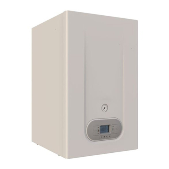
- Page 1 Installation, Use and Maintenance Manual for model R2K 50 Condensing boiler with integrated heat exchanger for domestic hot water production 0476 R2K 50 - RAD - ING - Manuale - 2107.1_SKM1.3_firm.L224G...
-
Page 2: Table Of Contents
SUMMARY SUMMARY INTRODUCTION 1. INSTALLER SECTION 1.1. INSTALLATION 1.1.1. GENERAL INSTALLATION WARNINGS 1.1.2. BOILER LOCATION ENVIRONMENTAL REQUIREMENTS 1.1.3. REFERENCE LEGISLATION 1.1.4. BOILER OVERALL DIMENSIONS 1.1.5. JIG 1.1.6. CIRCULATOR PREVALENCE/FLOW DIAGRAM 1.1.7. GENERATOR INSTALLATION 1.1.8. HYDRAULIC CONNECTION 1.1.9. SYSTEM FILLING 1.1.10. FILLING THE CONDENSATE COLLECTION SIPHON 1.1.11. - Page 3 SUMMARY 2.2.12. FAULT SIGNALLING CODES 2.2.13. ACTIVE FUNCTIONS SIGNALLING CODES 2.2.14. GAS CONVERSION 3. USER SECTION 3.1. USE 3.1.1. GENERAL USE WARNINGS 3.1.2. CONTROL PANEL 3.1.3. DISPLAY ICONS 3.1.4. INFO MENU DISPLAY DATA 3.1.5. START-UP 3.1.6. OPERATING MODE 3.1.7. INFORMATIONAL NOTE ON ANTI-FREEZE FUNCTION 3.1.8.
-
Page 4: Introduction
INTRODUCTION INTRODUCTION WARNING DANGER It identifies an information related to a Before starting any operation it is mandatory to general danger that if not complied with, may cause read this instruction manual, in relation to the serious personal damage or even death. activities to be carried out as described in each relevant section. - Page 5 INTRODUCTION › Energy labelling Directive 2010/30/CE, › Regulation EU 811/2013, MANUFACTURER WARRANTY AND RESPONSIBILITY › Regulation EU 813/2013, › Regulation EU 2016/426, The technical and functional features of the device › Electromagnetic compatibility Directive are ensured by its use in compliance: 2014/30/CE, with the use and maintenance instructions ›...
-
Page 7: Installer Section
1. INSTALLER SECTION 1. INSTALLER SECTION The installation operations described in this section, must be performed only by qualified personnel, having the appropriate technical training in the field for the installation and maintenance of components of civil and industrial domestic hot water production and heating plants. -
Page 8: Installation
1. INSTALLATION 1.1. INSTALLATION 1.1.1. GENERAL INSTALLATION › The device is suitable for use with the type of WARNINGS gas available by checking the boiler data plate (placed on the inner side of the front casing). ATTENTION This boiler may be used only for the ›... -
Page 9: Reference Legislation
1. INSTALLATION WARNING If the temperature in the appliance installation location goes below -10 centigrades, please fill the plant with anti-freeze liquid and insert and a frost prtotection kit (see chapter ‘ANTI-FREEZE PROTECTION’). WARNING The manufacturer will not be held responsible for damages caused by incorrect installation not in conformity with the above mentioned instructions and not duly protected from... -
Page 10: Boiler Overall Dimensions
1. INSTALLATION 1.1.4. BOILER OVERALL DIMENSIONS 1.1.5. JIG 84 57 HEATING RETURN Ø 1” 1/4 Ø 1/2 Ø 3/4 COLD Ø 1/2 HEATING FLOW Ø 1” 1/4 SC- CONDENSATE DRAIN Ø 25 mm... -
Page 11: Circulator Prevalence/Flow Diagram
1. INSTALLATION 1.1.6. CIRCULATOR PREVALENCE/FLOW DIAGRAM Wilo-Yonos PARA INT RS 25/8 FLOW RATE (m Appliance Loss... -
Page 12: Generator Installation
1. INSTALLATION 1.1.7. GENERATOR INSTALLATION MINIMAL TECHNICAL SPACES In order to allow the access inside the boiler for maintenance operations, you have to respect the minimum technical spaces indicated in figure 1. WARNING The incorrect slopes of the device can A - 200 mm cause the incorrect discharge of condensate by B - 300 mm... - Page 13 1. INSTALLATION WALL MOUNTING BY MEANS OF FIXING BRACKET WARNING In order to avoid condensate stagnations inside the condensate module, check that the boiler is slightly inclined towards the rear part (1-1.5°) in order to evacuate the condensate. WARNING The device must be installed only on a vertical solid wall, able to sustain its weight. In order to fix the thermal generator on the wall, proceed as follows: fix on the wall (fig.
- Page 14 1. INSTALLATION INSTALLATION ON SELF-SUPPORTING FRAME WARNING During the installation of the heat generator, pay maximum attention to the installation of the self-supporting frame. The frame must rest on a perfectly flat surface and, when supported against the wall, the latter must be perfectly angled. The incorrect slopes of the device can cause the incorrect discharge of condensate by means of the discharge duct with consequent condensate stagnation inside the condensate module.
-
Page 15: Hydraulic Connection
1. INSTALLATION 1.1.8. HYDRAULIC CONNECTION DOMESTIC CIRCUIT DANGER In order to prevent limestone build-up and Make sure that the tubes of the water and damages to the domestic water heat exchanger, heating plant are not used as grounding system for the hardness of the domestic supply water the electrical plant. -
Page 16: System Filling
1. INSTALLATION 1.1.9. SYSTEM FILLING WARNING For system filling use only clean tap water. WARNING If the system is filled by adding ethylene glycol-type chemical agents you have to install on the loading system a hydraulic trip unit in order to separate the heating circuit from the domestic circuit. -
Page 17: Filling The Condensate Collection Siphon
1. INSTALLATION open the air relief valves of the radiators and check the air removal process. When the water starts to leak close the radiators air relief valves. if after performing these operations you observe a decrease of the water pressure inside the system, open once again the loading tap “R”... -
Page 18: Anti-Freeze Protection
1. INSTALLATION 1.1.11. ANTI-FREEZE PROTECTION DILUTION PERCENTAGE CLEANPASS The boiler is protected against freezing thanks to FLUIDO AG the electronic board preparation with functions that start the burner and heat the concerned parts ANTIFREEZE - TEMPERATURE when their temperature goes below the minimum PROPYLENE GLYCOL FREEZING POINT pre-set values, protecting the boiler up to an... -
Page 19: Gas Connection
1. INSTALLATION 1.1.12. GAS CONNECTION 1.1.13. ELECTRICAL CONNECTION DANGER DANGER In order to connect the gas connector of The equipment is electrically safe only the boiler to the supply pipe use a stop seal of an if it is properly connected to an efficient grounding appropriate size and material. -
Page 20: Power Supply
1. INSTALLATION 1.1.14. POWER SUPPLY To power the boiler connect the electrical cables to the terminal inside the control panel as follows: DANGER Cut off the voltage from the main switch. › remove the boiler's front casing (refer to chapter ACCESSING THE BOILER). -
Page 21: Optional Electrical Connections
1. INSTALLATION 1.1.15. OPTIONAL ELECTRICAL CONNECTIONS The cables should be inserted inside the boiler using the cable glands ‘P1’ and ‘P2’ placed under the board (see fig. 1). Make a hole on the cable gland, smaller than the cable diameter, to make sure that the air cannot pass through. - Page 22 1. INSTALLATION To wire the optionals below: use the electronic board placed inside the control panel as follows: • (TP) EXCLUSION D.H.W. HEATING CIRCUIT VIA CLEAN CONTACT (SEE DANGER EXPLANATION IN THE PARAGRAPH ‘EXCLUSION Cut off the voltage from the main switch. VIA CONTACT (TP)’) ›...
- Page 23 1. INSTALLATION EXCLUSION VIA CONTACT (TP) In case there is a tank clock or a temperature thermostat connected on contacts n.55-56 of the M14 terminal board on the P.C.B., when the contact (TP) is closed, one of the following functions or requests can be excluded: FAST H2O FUNCTION –...
-
Page 24: Fume Exhaust Fittings
1. INSTALLATION 1.1.16. FUME EXHAUST FITTINGS › The discharge duct must be perpendicular with the opposite internal wall of the chimney or of WARNING the fumes exhaust duct (fig. 1). In order to ensure proper operation and efficiency of the device you have to connect the boiler fume exhaust fitting to the fume exhaust duct using appropriate polypropylene flue fittings for condensing boilers. -
Page 25: Types Of Fume Exhaust Systems
1. INSTALLATION 1.1.17. TYPES OF FUME EXHAUST SYSTEMS KIT AK 50 - HORIZONTAL CO-AXIAL SYSTEM Ø80/125 INTERNAL POLYPROPYLENE DUCT ADJUSTABLE AT 360°. It allows fumes discharge and air intake from external wall. Suitable only for condensing boilers. It allows fuel gas discharge and air intake for combustion through co-axial ducts, the external one for air intake, the plastic internal one for fumes discharge. - Page 26 1. INSTALLATION KIT CK 50 - VERTICAL CO-AXIAL SYSTEM Ø80/125 INTERNAL POLYPROPYLENE DUCT. It allows fumes discharge and air intake directly from roof. Suitable only for condensing boilers. It allows fuel gas discharge and air intake for combustion through co-axial ducts, the external one for air intake, the plastic internal one for fumes discharge.
- Page 27 1. INSTALLATION KIT EK 50 - SPLIT SYSTEM Ø80 MADE OF POLYPROPYLENE The two tubes system allows fumes discharge through the fumes exhaust duct and air intake from the environment. Suitable only for condensing boilers. It allows discharging fuel gas and air suctioning for combustion through two separated ducts.
- Page 28 1. INSTALLATION KIT FK 50 - SPLIT SYSTEM Ø80 MADE OF POLYPROPYLENE The two tubes system allows fumes discharge through the roof and air intake from the environment. Suitable only for condensing boilers. It allows discharging fuel gas and air suctioning for combustion through two separated ducts.
-
Page 29: Support Centre Section
1. SERVICE CENTRE SECTION 2. SUPPORT CENTRE SECTION All operations described below relative to first start- up, maintenance and replacement should be performed only by qualified personnel... -
Page 30: First Start-Up
2. FIRST START-UP 2.1. FIRST START-UP 2.1.1. PRELIMINARY OPERATIONS › make sure that there are no flammable liquids FOR FIRST START-UP or materials near the device; The first start-up operations consist in checking › open the boiler gas tap and make sure that there the correct installation, adjustment and operation are no gas leaks upstream from the device (the of the device. -
Page 31: Boiler Commissioning
2. FIRST START-UP 2.1.2. BOILER COMMISSIONING tube. Before repeating the operation, wait at least 5 seconds from the last start-up attempt WARNING and unlock the boiler from “E01” error code by Make sure that the system is correctly pressing the Reset ‘ ’... -
Page 32: Co2 Value Check And Calibration
2. FIRST START-UP 2.1.3. CO2 VALUE CHECK AND › Then press the key ‘ ’ of the heating CALIBRATION make sure that the CO value did not change to minimum, if changed repeat the calibration WARNING described in the previous paragraph. The CO value should be checked with the casing assembled, while the gas valve should be... -
Page 33: Accessing And Programming The Parameters
2. FIRST START-UP 2.1.4. ACCESSING AND PROGRAMMING THE PARAMETERS To access the parameters menu and adjust their values, follow the procedure below: Press the button ‘ ’ to select the OFF mode displayed using the symbol ‘ ’. Hold at the same time the keys ‘ ’... - Page 34 2. FIRST START-UP Use the keys ‘ ’ and ‘ ’ of the domestic circuit to change the value of the parameter. Press the key ‘ ’ to confirm the action and wait for the display to stop blinking, indication of the fact that the adjustment was implemented.
-
Page 35: Digitech Cs Parameters Table
2. FIRST START-UP 2.1.5. DIGITECH CS PARAMETERS TABLE PARAMETER DESCRIPTION RANGE FUNCTION BOILER MODEL SELECTION 0 = 13 KW 1 = 18 KW (HEAT.) / 24 KW (DOMESTIC) 2 = 25 KW 3 = 28 KW 4 = 34 KW 5 = 55 KW 6 = 100 KW 7 = R1K 18_24-R2K 24-R2KA 24... - Page 36 2. FIRST START-UP PARAMETER DESCRIPTION RANGE FUNCTION GAS TYPE SELECTION 0 - 1 0 = NATURAL GAS ATTENTION: READ THE INSTRUCTION IN CHAPTER ‘GAS CONVERSION’ BEFORE CHANGING THIS PARAMETER. 1 = LPG SETTING THE HEATING TEMPERATURE 0 - 1 0 = STANDARD (30-80 °C) IN CASE THE BOILER IS INSTALLED AS PART OF A LOW (SET BY DEFAULT) TEMPERATURE...
- Page 37 2. FIRST START-UP PARAMETER DESCRIPTION RANGE FUNCTION POST-CIRCULATION HEATING TIMING 0 - 90 VALUE EXPRESSED IN THROUGH THIS PARAMETER, IT IS POSSIBLE TO SET THE MULTIPLES OF 5 SECONDS OPERATION TIME OF THE PUMP AFTER THE MAIN BURNER (PRE-SET AT 36 X 5 = 180 TURNS OFF DUE TO THE ENVIRONMENT THERMOSTAT.
- Page 38 2. FIRST START-UP PARAMETER DESCRIPTION RANGE FUNCTION HEATING FAN MAXIMUM SPEED ADJUSTMENT SEE CHAPTER THE VALUE IS EXPRESSED IN THROUGH THIS PARAMETER YOU CAN SET THE FAN MAXIMUM ‘ HERTZ SPEED IN HEATING PHASE, THAT CORRESPONDS TO THE C A P A C I T Y (1HZ = 30 RPM) MAXIMUM BURNER POWER DURING A REQUEST TO OPERATE D I A G R A M...
- Page 39 2. FIRST START-UP PARAMETER DESCRIPTION RANGE FUNCTION CLIMATE COMPENSATION CURVE 0 - 30 (SET BY DEFAULT AT 25) THE (ONLY WITH EXTERNAL PROBE CONNECTED) NUMBERING OF THE VALUE YOU CAN CONNECT AN EXTERNAL TEMPERATURE PROBE (SEE CORRESPONDS TO ‘KD’ CURVES CHAPTER ‘ELECTRICAL CONNECTIONS’) THAT AUTOMATICALLY ON THE CHART (SEE CHART CHANGES THE DELIVERY TEMPERATURE BASED ON THE...
- Page 40 2. FIRST START-UP PARAMETER DESCRIPTION RANGE FUNCTION DISABLEMENT OF DOMESTIC HOT WATER LINE BY MEANS OF 0 - 1 0 = DISABLED SWITCH (ONLY FOR FAST BOILERS) (SET BY DEFAULT) (SEE EXCLUSION VIA CONTACT (TP) IN THE CHAPTER “OPTIONAL ELECTRICAL CONNECTIONS”) 1 = ENABLED BY ENABLING THIS PARAMETER IN THE PRESENCE OF A CONNECTION (FOR EXAMPLE A BOILER CLOCK OR A...
- Page 41 2. FIRST START-UP PARAMETER DESCRIPTION RANGE FUNCTION MODULATING PUMP MINIMUM SPEED 50 - 70 THE VALUE IS EXPRESSED IN (ONLY WITH MODULATING PUMP AND RETURN PROBE CONNECTED) PERCENTAGE THROUGH THIS PARAMETER YOU CAN SET THE MINIMUM SPEED VALUE OF THE MODULATING PUMP DURING A REQUEST TO OPERATE IN HEATING MODE.
- Page 42 2. FIRST START-UP PARAMETER DESCRIPTION RANGE FUNCTION T HEATING POSTCIRCULATION 0 - 25 THE VALUE IS EXPRESSED IN °C THROUGH THIS PARAMETER, IT IS POSSIBLE TO SET THE (SET BY DEFAULT AT 10 °C) TEMPERATURE DIFFERENCE FROM THE MAIN BURNER SHUTOFF, FOR THE INTERVENTION OF THE ROOM THERMOSTAT, TO THE DISABLING OF THE PUMP IN HEATING MODE.
- Page 43 2. FIRST START-UP PARAMETER DESCRIPTION RANGE FUNCTION ACTIVATION OF THE AUXILIARY RELAY ON THE “SVZ” P.C.B. (SEE 0 - 4 0 = DISABLED (SET BY DEFAULT) CHAPTER: OPTIONAL ELECTRICAL CONNECTIONS) 1 = HEATING CIRCUIT BOOSTER THROUGH THIS PARAMETER IT IS POSSIBLE TO MANAGE THE PUMP TYPE OF FUNCTIONING OF THE AUXILIARY RELAY ON THE 2 = D.H.W.
-
Page 44: Electric Fan Frequency/Heat Capacity Diagram
2. FIRST START-UP 2.1.6. ELECTRIC FAN FREQUENCY/HEAT CAPACITY DIAGRAM FREQUENCY (Hz) STARTING STEP GAS TYPE MINIMUM FREQUENCY MAXIMUM FREQUENCY ADJUSTMENT... -
Page 45: Maintenance
2. MAINTENANCE 2.2. MAINTENANCE 2.2.7. GENERAL MAINTENANCE › check the primary exchanger, if necessary, clean WARNINGS DANGER › check the operation of the gas light up and safety Before each components cleaning or systems. If necessary, remove and clean the replacement operation, ALWAYS cut off the POWER, flame detection and light up electrodes from WATER and GAS supply of the boiler. -
Page 46: Technical Data
2. MAINTENANCE 2.2.8. TECHNICAL DATA Model R2K 50 CE certification 0476CQ0134 Gas category (IT) II2H3B/P Flue system type type B 2 3 - B 2 3 p - B 3 3 - B53-C13-C33-C43- C 5 3 - C 6 3 - C 7 3 -... - Page 47 2. MAINTENANCE Weighted NOx (0% O2) on GCV mg/kWh mg/kWh Central heating circuit Temperature setting - Central heating °C 30-80 / 25-45 Max. operating temperature - Central heating °C Max. operating pressure - Central heating Min. operating pressure - Central heating Domestic Hot Water (D.H.W.) circuit Temperature setting - D.H.W.
- Page 48 2. MAINTENANCE Flue bend 90° MF Ø80 - Pressure loss Flue extension MF Ø80 L=1000 - Pressure loss T-connection MF Ø80 - Pressure loss Max. Flue length Ø100 - Horiz. Pipe Electrical specifications Voltage-frequency V/Hz 220-230/50 Electric power with boiler OFF Max Power consumption Max Power consumption - boiler pump (100%) Protection rating...
-
Page 49: Technical Assembly
2. MAINTENANCE 2.2.9. TECHNICAL ASSEMBLY FUMES SAFETY THERMOFUSE HEAT EXCHANGER BURNER UNIT DETECTION ELECTRODE AIR SUCTION TUBE PROPORTIONAL VENTURI CIRCULATOR CONDENSATE COLLECTION SIPHON SYSTEM DRAINING TAP 10. GAS VALVE 11. AUTOMATIC AIR RELIEF VALVE 12. SAFETY THERMOSTAT 13. HEATING PROBE 14. -
Page 50: Internal Piping Schematic
2. MAINTENANCE 2.2.8. INTERNAL PIPING SCHEMATIC fig. 1 16. CONDENSATE COLLECTION SIPHON R. CENTRAL HEATING RETURN 17. WATER PRESSURE SWITCH C. DOMESTIC HOT WATER OUTLET 18. DIVERTER VALVE G. GAS INLET 19. BY-PASS SC. CONDENSATE DRAIN 20. FLOW SWITCH F. COLD WATER INLET 21. -
Page 51: Wiring Diagram
2. MAINTENANCE 2.2.9. WIRING DIAGRAM 220 V 50 Hz Pacq ER: DETECTION ELECTRODE TS: SAFETY THERMOSTAT MP: PANEL TERMINAL CE: BLUE EA: START-UP ELECTRODE PACQ:WATER PRESSURE SWITCH SE: EXTERNAL PROBE MA: BROWN PM: MODULATING PUMP MF: MICRO-FLOW SWITCH TA: ENVIRONMENT THERMOSTAT AR: ORANGE VG: GAS VALVE SR: HEATING PROBE... -
Page 52: Accessing The Boiler
2. MAINTENANCE 2.2.13. ACCESSING THE BOILER For the majority of the control and maintenance operations you have to remove one or more panels of the casing. The side panels can be removed only after removing the front panel. To intervene on the front of the boiler proceed as follows: ›... -
Page 53: Accessing The Electronic Board
2. MAINTENANCE 2.2.10. ACCESSING THE ELECTRONIC BOARD In order ot intervene on the wirings of the control panel, please proceed as follows: DANGER Cut off the voltage from the main switch. › Grab at the same time the support brackets of the control panel (fig. -
Page 54: System Emptying
2. MAINTENANCE 2.2.11. SYSTEM EMPTYING HEATING SYSTEM EMPTYING Whenever you need to empty the system, proceed as follows: › switch the boiler to “WINTER” mode and activate it; › turn off the main power supply switch; › wait for the boiler to cool down; fig. -
Page 55: Fault Signalling Codes
2. MAINTENANCE 2.2.12. FAULT SIGNALLING CODES To view the last 5 fault signalling codes chronologically, starting with the most recent one, activate the ‘OFF’ mode by pressing the FUNCTION ‘ ’ key and hold the key INFO ‘ ’ for 5 seconds. Use keys ‘ ’... - Page 56 2. MAINTENANCE CODE FAULT POSSIBLE CAUSE SOLUTION RESET SAFETY THERMOSTAT THERMOSTAT CABLE CHECK THE WIRING: AUTOMATIC. (95°C) DISCONNECTED; BROKEN THERMOSTAT. REPLACE IT. FUMES SAFETY THERMOFUSE BROKEN; REPLACE IT; MANUAL RESET THERMOFUSE (102°C) (PRESS THE RESET THERMOFUSE CABLE CHECK THE WIRING. ‘...
- Page 57 2. MAINTENANCE CODE FAULT POSSIBLE CAUSE SOLUTION RESET AIR PRESSURE SWITCH PRESSURE SWITCH CHECK THE WIRING; MANUAL RESET CABLE DISCONNECTED; (PRESS THE RESET ‘ ’ KEY). DISCHARGE OR SUCTION CHECK THE FUMES DISCHARGE DUCT; CLOSED; AIR PRESSURE SWITCH REPLACE IT. DEFECTIVE.
- Page 58 2. MAINTENANCE CODE FAULT POSSIBLE CAUSE SOLUTION RESET COMMUNICATION ERROR NO ELECTRICAL CHECK THE WIRING; AUTOMATIC. BETWEEN THE BOILER CONNECTION; BOARD AND THE MODBUS BOARD MODBUS BOARD BROKEN; REPLACE IT; RESIDUAL FLAME FAULTY DETECTION CLEAN IT OR REPLACE IT; MANUAL RESET ELECTRODE;...
-
Page 59: Active Functions Signalling Codes
2. MAINTENANCE 2.2.13. ACTIVE FUNCTIONS SIGNALLING CODES CODE FUNCTION DESCRIPTION CHIMNEY SWEEP ACTIVE YOU CAN ACTIVATE IT BY HOLDING FOR 7 SECONDS THE RESET ‘ ’ KEY AND YOU CAN DEACTIVATE IT BY TURNING OFF THE BOILER. THIS FUNCTION BRINGS THE BOILER TO ITS MINIMUM AND MAXIMUM HEATING POWER FOR 15 MINUTES DEACTIVATING THE MODULATION FUNCTION. -
Page 60: Gas Conversion
2. MAINTENANCE 2.2.14. GAS CONVERSION ATTENTION Make sure that the gas adduction tube is suitable for the new type of fuel with which the boiler is supplied. › loosen the two screws ‘1’ (fig.1) from the fastening bush, and remove the air suction tube; ›... -
Page 61: User Section
1. USER SECTION 3. USER SECTION The operations described in this section are addressed to all those who will use the machine. The machine must be used and accessed only by qualified operators that fully read and understood the User section, paying particular attention to the warnings. -
Page 62: Use
3. USE 3.1. USE 3.1.1. GENERAL USE WARNINGS › DO NOT use electrical switches, the telephone or any other device that might generate electrical WARNING discharges or sparks; Before starting the boiler the User must make sure that the First start-up certificate has the ›... -
Page 63: Control Panel
3. USE 3.1.2. CONTROL PANEL DISPLAY HEATING TEMPERATURE ADJUSTMENT KEYS INFO KEY: PRESS ONCE TO VIEW THE TEMPERATURES AND OTHER INFORMATION (see chapter ‘INFO MENU DISPLAY) - HOLD FOR 5 SECONDS, IN OFF OPERATING MODE, TO VIEW THE LAST 5 FAULTS OPERATING MODE SELECTION KEY: SUMMER / ONLY HEATING / WINTER / OFF RESET KEY: FAULTS RESET -... -
Page 64: Display Icons
3. USE 3.1.3. DISPLAY ICONS INDICATION OF PARAMETER NUMBER OR DISPLAYED INFO CODE PARAMETERS PROGRAMMING FUNCTION ACTIVE SIGNALLING CONNECTED SOLAR BOARD / SOLAR COLLECTOR TEMPERATURE DISPLAY (d5) fig. 1 SOLAR PUMP ACTIVE BOILER LOWER TEMPERATURE DISPLAY (d6) / BOILER UPPER TEMPERATURE DISPLAY (d7) EXTERNAL PROBE INSTALLED / EXTERNAL ≤... -
Page 65: Info Menu Display Data
3. USE 3.1.4. INFO MENU DISPLAY DATA To view the boiler data from info menu you just have to press the INFO ‘ ’ key. The info code will be displayed on the left side of the screen and its relative value will be displayed on the centre of the screen. Use keys ‘... -
Page 66: Start-Up
3. USE 3.1.5. START-UP WINTER MODE Before starting the boiler make sure that it is In this mode the boiler meets the demands of powered and that the gas tap below the boiler is heating and of domestic hot water. open. -
Page 67: Informational Note On Anti-Freeze Function
3. USE 3.1.7. INFORMATIONAL NOTE ON pump anti-locking and diverter valve anti-locking ANTI-FREEZE FUNCTION systems still remain active. To switch the boiler to OFF operating mode, press The boiler is protected against freezing thanks to the function key ‘ ’, the symbol ‘ ’... -
Page 68: Fault Signalling Codes
3. USE 3.1.8. FAULT SIGNALLING CODES The boiler might signal some faults by displaying a code. Below you have a list of the codes and of the operations to be performed in order to unlock the boiler. CODE ICON FAULT INTERVENTION FLAME BLOCK MAKE SURE THAT THE BOILER AND CONTACTOR GAS VALVES... - Page 69 3. USE CODE ICON FAULT INTERVENTION GENERAL INTERNAL BOARD ERROR CUT OFF THE POWER SUPPLY FROM THE MAIN SWITCH AND THEN RESTORE IT, AS SOON AS THE ERROR CODE DISAPPEARS, THE BOILER WILL RESTART AUTOMATICALLY. IF THE BLOCK PERSISTS CONTACT THE TECHNICAL SUPPORT CENTRE.
-
Page 70: Active Functions Signalling Codes
3. USE 3.1.9. ACTIVE FUNCTIONS To activate/deactivate the Fast H2O function please SIGNALLING CODES follow the instruction indicated in the paragraph ‘ACTIVE FUNCTIONS SIGNALLING CODES’. CODE FUNCTION INTERVENTION H E A T I N G WAIT UNTIL A N T I - F R E E Z E OPERATION IS COMPLETED FUNCTION ACTIVE D.H.W... -
Page 71: Maintenance
3. USE 3.1.11. MAINTENANCE To ensure proper boiler safety and efficiency, please contact technical support network to check the device every year. An accurate maintenance should improve system management. 3.1.12. EXTERNAL CASING CLEANING Clean the cover of the device using a wet cloth and come neutral soap.
Need help?
Do you have a question about the R2K 50 and is the answer not in the manual?
Questions and answers