
Related Manuals for Flexiheat CITY BOX 25 K


Summary of Contents for Flexiheat CITY BOX 25 K
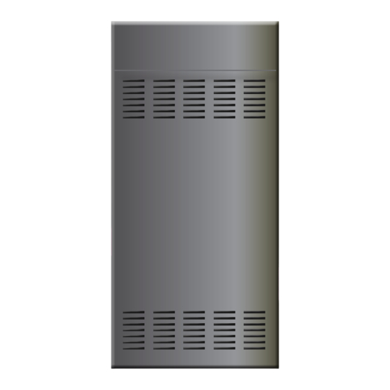
- Page 1 SLIM SOLAR instruction Handbook installation adjustment maintenance CITY BOX 25 k 35 k CITY BOX Green Heating Technology...
-
Page 2: Table Of Contents
Table of Content Safety warnings 3 Gas connection � � � � � � � � � � � � � � � � � � � � � � � � � � � 18 Electrical connections � � � � � � � � � � � � � � � � � � � � � � 19 Safety warnings symbols legend ... -
Page 3: Safety Warnings
Safety warnings This instructions manual is an essential and complementary part of the product and it is supplied together with the boiler� Carefully read the manual, achieving all important information for a safe installation, use and servicing� f Carefully keep the manual, together with the documentation of all the accessories of the boiler and of the system, for any further consultation you may need. -
Page 4: Safety Warnings Symbols Legend
Safety warnings symbols legend Generic safety Electrical danger Physical danger warning (fulguration) (personal damage) Thermal danger General warning or advice to avoid material damage (burns) or to achieve improvements References to Laws and Norms All references to laws and laws contained in this handbook, as well as all installation, maintenance and use prescriptions and the relevant pictures, are relevant to European and/or Italian regulation. -
Page 5: User Warnings
User warnings Important In case of gas smell: 1 - do not press electrical switches, use the telephone or other objects that can provoke sparks; 2 - open immediately the windows and the doors in order to cleanse the room air; 3 - close the gas supply taps;... -
Page 6: Installation, First Starting Up, Maintenance And Servicing
f Do not expose the wall hung gas boiler to water or other liquids sprinklings, or to vapours directly coming from gas cookers/hobs� f Do not obstruct the air intake or flue outlet terminals, even momentarily or partially. f Do not put any object on the gas boiler and don't leave any flammable liquid or solid materials, (e.g. paper, clothes, plastic, polystyrene) in its proximity. -
Page 7: User Guide
User guide Boiler controls Remote control All user controls of the boiler are located in the Remote Control, which is supplied with its own instruction manual. For the description of all controls and for the boiler management operations that are not included in this booklet, refer to the instruction manual of the Remote Control. -
Page 8: Service Control Panel
Service Control Panel The electric box that contains the electronic control unit (pos. 13 on page 52) is complete with standard controls. It cannot be accessed from the outside, but it is a useful control panel that can be used by the Technician in the following cases: •... -
Page 9: The Burner Doesn't Turn On
The burner doesn’t turn on f Check whether the Remote Control uses an alarm code; in this case, depending on the code, try to restore the operation as described in paragraph “Alarms - boiler block" on page 41. f If the Remote Control display is completely off, the Remote Control connection may be insufficient, but first make sure that the power supply omnipolar switch of the boiler is not turned off or that there are no other power supply interruptions. -
Page 10: Off Mode With Anti-Frost & Anti-Locking Function
Remark: the boiler is equipped with a system which protects the main components from the exceptional cases of mechanical lock, due to the inactivity in presence of water and scale. The anti-locking function can’t work in Safety shut off mode, because of the lack of electrical supply. Before switching on the boiler again, have the circulating pump checked by a technician to make sure it is not blocked due to inactivity (for the technician: proceed as described in paragraph “Circulating pump rotor unlocking"... -
Page 11: Installation
We recommend that you completely empty the hot and cold sanitary water system, including the sanitary circuit and the boiler’s sanitary exchanger. The anti-frost function does not protect the sanitary circuit outside the boiler. Installation Law and regulation prescriptions for the installer Always comply with national and/or local regulation about BOILER INSTALLATION. -
Page 12: Warnings For The Installation Of Optional Kits Or
(see par. 35 on page 35) and are net of the load loss of the circuits inside the boiler. The area represents the working range with pump City Box 25 K in modulating mode (see par. 33 on page 34) 1000 1200... -
Page 13: Dimensions And Connections
Dimensions and connections The boiler is flush-mounted, using exclusively the flush-mounted box and the original connection kit. Flue system - precut holes of the flush-mounted unit 1 Coaxial system (air intake + flue outlet) 2 Flue outlet, split-pipe or B22 3 Air intake, split-pipe Hydraulic and electric connections on the flush-mounted box lower side... -
Page 14: Protection Against Freezing
Protection against freezing Boiler is protected from freezing through functions set in the control equipment that heat the con- cerned parts when temperatures go below the minimum values predefined in the factory. The temperatures of the heating circuit inside the boiler (primary circuit) and of the domestic water circuit are detected by the same probes that control their operations. -
Page 15: Installation Of The Thermal Unit Into The Flush
Flush-mounted box positioning and fastening Depending on the depth of the wall, create a recess or an opening of the same dimensions as the flush-mounted box and a space under it, so that connections can be carried out. See measures in paragraph “Dimensions and connections"... -
Page 16: Hydraulic System (Dhw And Heating)
Hydraulic system (DHW and heating) Make sure that the hydraulic and heating systems ducts are not used as earth connections of the electrical system. They are absolutely NOT SUITABLE for such a use. Besides: they don't guarantee the earth dispersion; in case of electrical fault they could generate a fulguration risk; there could take place galvanic currents in the pipings and consequent corrosion and hydraulic leaks�... -
Page 17: Condense Drain
Condense drain Insert the flexible pipe of condense outlet inside the outlet funnel (or other inspectable connection device) properly installed for this purpose, or in the outlet funnel of the safety valve, in case of the above mentioned outlet is able to receive the acid liquids of the condense as foreseen by the norms in force in matter of condensing boilers. -
Page 18: Gas Connection
Gas connection Due to various installation possibilities, the gas cock 3 supplied with the original Connections Kit has a simple male Ø ½” connection, facing the rear of the boiler. The gas pipe 4, upstream the gas cock 3, should be supplied by the installer. While connecting the gas inlet of the boiler to the gas supply piping, it is MANDATORY to insert a PLAIN GASKET, whose dimensions and material must be adequate. -
Page 19: Electrical Connections
Electrical connections The link of the Remote Control works with a safety extra low voltage (SELV); connect it to the supplied Remote Control only, as the boiler can't work without it. On NO account must any electrical voltage be applied to these terminals� To avoid malfunctions due to electrical noise, the Remote Control connections, as well as all low-voltage connections, should be kept separated from power supply cables, e.g. -
Page 20: Remote Control Installation And Connection
Remote Control installation and connection Extract the Remote Control from its package. Keep the relevant user instruction booklet and annex it to this Manual. To avoid malfunctions due to electrical noise, the Remote Control connections should comply with the following requirements: •... -
Page 21: Flue Systems
Flue systems intake for Intake/outlet flange split system The boiler is equipped with a flange for connecting inlet and outlet flues pipes; this flange has been studied for collecting rain/water that may creep into the inlet pipe and for avoiding that rain reaches the burner’s fan. -
Page 22: Sizing C 63 Systems
Air intake and flue outlet terminals should be protected by suitable approved flue accessories, to avoid environmental elements penetration. Carefully follow the indications foreseen by the specific laws in force. Respect the minimum and maximum flue length prescribed (see “Sizing the flue system" on page 24). In case of flue outlet on wall, the positions and the distances prescribed by the regulation mist be respected�... -
Page 23: Examples Of Installation Of Intake And Outlet Ducts
Examples of installation of intake and outlet ducts We give you some correct and wrong examples of installation of intake and outlet ducts for condensing boilers (the slope are voluntarily represented in an exaggerated way). A = Intake; S = Outlet. 1: the most functional and economic solution is to let the condense come back towards the boiler**�... -
Page 24: Sizing The Flue System
Sizing the flue system Split pipe system (C * and B Examples of split pipe systems C ATTeNTIoN: use the Inlet Connection without Bend, as shown in the figure, for this so- lution only. In all other cases, insert it into the bend�... -
Page 25: System Length Tables
f The data differ according to the diameter of the inlet and outlet system and the type of ducts used: rigid (smooth) or with flexible pipe (corrugated). Systems consisting of mixed duct types are not considered f The boiler, with factory settings, covers a range of lengths that meets most of the applications. If nec- essary, it is possible to change some operating parameters to satisfy an increased range of lengths. -
Page 26: Allowed Flue Types
Allowed flue types max 0,5 m B23P B53P The flue duct and its connection to the Separated outlet and inlet, in shared chimney should be made in compliance chimneys subjected similar wind to National and Local Regulation in conditions (natural draught chimney). The force. –... -
Page 27: Adjustment And Maintenance
Adjustment and Maintenance WARNING: Hereby described operation can be performed by qualified technicians only. When regulation/measuring is over, remember to verify the absent of gas leakages. Do not use free flames to detect gas leakages The gas valve, exception the PIN plug and the upwards connections, works in NEGATIVE PRESSURE. -
Page 28: Maintenance Operations
f verify the presence of the permanent air/ventilation outlets, correctly dimensioned and working, as foreseen by the National and Local laws depending on the appliances installed; f verify that the evacuation flue duct corresponds to the National and Local laws and that is in good and efficient conditions;... -
Page 29: Access To The Inside Of The Boiler
f verify that the passage of the air burning and the evacuations of the flues and of the condense will be made correctly according to National and Local laws in force; f verify the correct functioning of the system of the outlet condense, also in the external parts of the boilers, i.e. -
Page 30: Venting The Primary Exchanger
Venting the primary exchanger When commissioning the boiler, we recommend to check that there is no air in the primary circuit of the combustion unit. Do this operation also during the combustion unit cleaning, if you hear the typical air bubble noise. f Locate the combustion unit manual venting valve (item 9 in the following picture) and, to avoid wetting the boiler inside, insert a length of flexible hose, with suitable diameter, on its fitting, then direct the other end towards a drain (or a container to collect the anti-freeze solution);... - Page 31 f loosen the clamp 15 and pull the flexible air intake hose 16 out from the fan; f unscrew, following the stamped sequence, the four nuts 1 which fix the burner group 20 (composed of fan, hose and burner) to the primary exchanger. Remove the burner group; Do not disassemble the burner group and do not dismount the ceramic fibre plate from the bottom of the exchanger.
-
Page 32: Pcb Parameters Settings (Technician Menu)
PCB parameters settings (technician menu) Boiler parameter setting is to be carried out by technical personnel only. The technical menu is accessible from the Service Control panel through a specific key combination owned by the technician. A few of these settings allow to optimise and tailor the boiler working, while a few others allow to set the boiler during maintenance operation. - Page 33 Parameter Adj. range Description (fact. set.) and values 0…2 (0) Pump functioning mode during heating working intermittent for normal applications (with eventual delay defined by parameter 06) always on (to fit the needs of particular plants) always off (use only when external pumps are foreseen). Remark: The pump will be anyway activated in all other circumstances, e.g.
- Page 34 Parameter Adj. range Description (fact. set.) and values 20…80 TA2 input setting (flow temperature during a CH request from the Secondary Room Thermostat only) The boiler can manage a secondary room thermostat installed in a zone that must be heated with a different typology compared to the one where the primary room thermostat (or the original Remote Control) is installed.
- Page 35 Parameter Adj. range Description (fact. set.) and values Maximum power of modulating pump. It is recommended not to change 65…99 factory setting. mod. 25: mod. 30: While minimum pump power is fixed at 65% of the nominal maximum, the maximum pump power can be reduced to solve particular installation (eg. plant noise), provided that the pump modulation is enabled.
-
Page 36: Combustion Test
Combustion test if burner and exchanger cleaning is foreseen, carry it out before testing the combustion (see “Combustion group cleaning and check" on page 30. To perform the test you need a flue analyser, correctly calibrated (in the condensing boiler, the precision and the correctness of the measures is particularly important). -
Page 37: Power Adjustment Tables
if one or more CO values was outside allowed ranges, carry out the MANUal combustion calibration (see “Combustion calibration" on page 38); • if the manual calibration doesn't allow to adjust the CO to normal values, carry out an AUTOmatic calibration (remove the analyser during this operation) and then do a manual calibration again, measuring and adjusting the CO . -
Page 38: Combustion Calibration
5. To switch the burner off, quit the technician menu (see also “PCB parameters settings (technician menu)" on page 32). The boiler switches to OFF mode. The MAX power for the heating system is adjusted now. Combustion calibration Boiler is able to self-calibrate combustion in order to obtain correct CO values on 3 different boiler power (minimum, average, maximum);... -
Page 39: Accessing The Main Board
Gas G20 (1) Conv. to G31 (2) Conv. to G230 (2) configuration 30140 31140 32140 City Box 25 K codes 30340 31340 32340 City Box 35 K (1) Factory preset; code written on the sticker on the electronic box (2) Code that will appear on the display (for some seconds at the moment of the electrical supply) if the Parameter 01 has been changed because of gas conversion. -
Page 40: Gas Conversion
Gas conversion ATTENTION: the operations described below must be carried out only by qualified personnel. This boiler is designed and prepared to be supplied with Natural Gas G20 (Methane). It can be set, just by means of electronic settings, but always by a qualified technician, to operate with Commercial Propane G31 or Air/Propane G230, for which it is absolutely necessary to install a pressure reducer upstream the boiler. -
Page 41: Draining The Heating System
Draining the heating system When it is necessary to drain the heating system, proceed as described here below: Cut off the supply voltage to the boiler, for safety reasons, but also to prevent the activation of the automatic system of the filling system. - Page 42 electrical supply to the boiler for 30 seconds, by using the purposed external switch, but should the alarm happen again, it will be necessary to call the Service Centre. Operations accompanied by the symbol are always reserved to the Technician. Operations with grey background are reserved to the Technician.
- Page 43 Signal Probable causes Suggested solutions Combustion check User: Try only one boiler reset by using the button. anomaly� Gas valve If the lockout persists or reappears, call the Service Centre for re- is supplied without quired procedure flame presence. Failure Check the cabling of the system flow temperature probe.
- Page 44 Signal Probable causes Suggested solutions Pushbutton failure Check the Service Control Panel (see “The Service Control Panel" Service on page 55) for jammed pushbuttons that remain pressed. Control Panel� Disconnect the electrical supply to the boiler by operating the suitable external bipolar switch, then connect it again after a few electronic minutes.
- Page 45 Signal Probable causes Suggested solutions Inlet electrical fre- quency not correct Call Service Centre for checking electric inlet signal� (50 Hz ± 1 Hz). Floor heating system The floor heating system and the floor cladding can be damaged by safety thermostat temperature shocks, so a good quality system includes one or more triggering:...
- Page 46 Signal Probable causes Suggested solutions Unexpected flame Wait for the boiler automatic reset (5 minutes) or reset it manually by using the button. If the lockout persists or reappears, call control the Service Centre� electronic detected the flame on the burner when Detect eventual malfunctioning of the gas valve (that does this one should be not stop fully the gas flow, so the burner remains ignited) or of...
- Page 47 Signal Probable causes Suggested solutions Return and flow probes inverted� Call Service Centre for required procedure. Check CH probes (Flow and Return). Max number of no-flame detection events has been reached, mainly during the combu- stion internal check cycle� Refer to Alarm E08 for the probable causes and for the boiler reset actions suggested.
-
Page 48: Warnings For Servicing
Warnings for servicing All servicing operations and gas conversions MUST BE CARRIED OUT BY QUALIFIED TECHNICIANS, in compliance with the norms and laws in force (see an indicative list on page 4). Moreover, MAINTENANCE operations must be carried out in compliance with the manufacturer prescriptions and with the laws and rules presently in force, for the parts not mentioned in this handbook;... -
Page 49: Erp Data - Eu 813/2013
ErP Data - EU 813/2013 Supplier name: Italtherm City Box City Box Model(s): Contact details: Italtherm S.p.A. – Via Salvo D'Acquisto – 29010 Pontenure (PC) – Italy 25 K 35 K ErP Data - EU 813/2013 Symbol Unit Value Value Condensing boiler Yes/No Combination heater Yes/No... -
Page 50: Technical Data
Qmin Minimum heat input (both in heating and DHW modes) system return / flow water temperature NCV Net Calorific Value (=Hi) Remark: data have been measured with horizontal coaxial flue, length = 1 m TECHNICAL DATA City Box 25 K City Box 35 K U.M. Gas type G230... - Page 51 TECHNICAL DATA (cont'd) City Box 25 K City Box 35 K U.M. Gas type G230 G230 Expansion vessel Expansion vessel pre-loading pressure 0.5 / 1.2 0.5 / 1.2 (±0.2) (±0.2) Loss of water pressure switch To allow the correct system filling, the pressure of the domestic water should be higher off / on pressure than the ON value of the pressure switch.
-
Page 52: Boiler Internal Components
Boiler internal components 18 Drain valve Plug for Combustion analysis (air intake) 19 Gas valve Plug for Combustion analysis (flue) 20 DHW exchanger Flue overheat fuse 21 DHW flow regulator Water drain pipe from air intake flange 22 DHW temperature sensor Air intake hose 23 Filling valve, manual 24 System pressure gauge... -
Page 53: Electrical Diagram
Electrical diagram 16.2 16.1 3 28 Optional external devices: Flue overheat fuse SE To optional outdoor temperature sensor 6.1 Fan - supply TA2 To optional room thermostat for zones with 6.2 Fan - speed control different temperature range Temperature Sensor on system return AUX Input for optional device, configurable with 10 Electric heaters Parameter 46 (see page 35). -
Page 54: Hydraulic Diagram
Hydraulic diagram 29 Motorized 3-way valve Water drain pipe from air intake flange 30 Safety thermostat on system flow Air intake hose 31 Air/Gas Mixing device 32 Expansion Vessel Temperature Sensor on system return 35 Flue connection flange Siphon for condense outlet 51 Flue hood 11 System filling electrovalve 52 Combustion chamber... -
Page 55: Addendum
Addendum Outdoor Sensor Kit Installation and setting The Outdoor Sensor manages automatically the CH flow temperature** as a function of the outdoor temperature, thus avoiding the user to adjust it manually. This function is also named "shifting temperature"� that's the temperature of the heating elements. Don't mistake it with the room temperature (managed by the Remote Control as well) that doesn't depend on the first one. - Page 56 Pushbuttons (** = functions available only when the Remote Control is disabled or not detected) Stand-by / Functioning mode Every time it is pressed, the boiler cyclically switches from the OFF mode to “Summer – Remote Control” and “Winter” operating modes.
-
Page 57: Boiler And Remote Control Activation
Three digit display under the symbol Normally, it displays the temperature of the hot water on boiler's outlet. When the boiler is in manual stand-by mode, it displays During the DHW temperature** setting (by pressing the buttons ), it shows the temperature value changing; in case of alarm it displays the ID number of the alarm (see “Alarms - boiler block"... -
Page 58: Temperature Adjustment (Manual Working Modes)
• Winter (manual) MODE . This mode is required for: ◦ technical operations requiring forced ignition of the burner. ◦ moreover, this mode can be used temporarily in case of Remote Control malfunction during the winter period, to fulfil the needs for domestic hot water and heating. Please, consider that heating will be activated only upon the closure of a voltage-free contact (of an ambient thermostat or of a timed thermostat) connected to CR terminals that are normally intended for the Remote Control - see “Electrical diagram"... -
Page 59: Modulating Circulating Pump - Details
Modulating circulating pump - details The circulating pump is electronically controlled and receives power supply and "PWM" speed control signal over two different connectors� The front cap features a hole with pin to unlock the rotor 2 and, depen- ding on the model, a two-colour status light indicator 1� Status indicator When present, indicator 1 can be: off - the circulating pump does not receive voltage on the power supply... -
Page 60: Appliance Disposal
Appliance disposal At the end of its life, the product must not be di- sposed of as solid urban waste but must be sent to a separate collection centre. Notes Green Heating Technology... - Page 61 Notes Green Heating Technology...
- Page 62 Notes Green Heating Technology...
- Page 63 Notes Green Heating Technology...
- Page 64 Green Heating Technology www.italtherm.it ITALTHERM S.p.A. | Via S. D’Acquisto | 29010 Pontenure (PC) Italy | P.iva - C.F. 01594830331 | Tel (+39) 0523.575611 | www.italtherm.it...