
Related Manuals for Flexiheat ThermoExtra 28 kW


Summary of Contents for Flexiheat ThermoExtra 28 kW
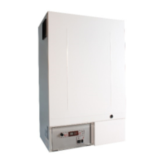
- Page 1 ELECTRIC BOILERS FOR CENTRAL HEATING ThermoExtra 28-96kW INSTRUCTIONS FOR INSTALLATION AND USE INSTRUCTIONS FOR INSTALLATION AND USE TMS-UT-0621-Z01-1 We reserve the right of alternations...
- Page 2 INSTRUCTIONS FOR INSTALLATION AND USE TMS-UT-0621-Z01-1 We reserve the right of alternations...
-
Page 3: Table Of Contents
Contents General ..........................6 1. Introduction ........................7 1.1. Applicable documents ....................7 1.2. Retention of documents ....................7 1.3. Introduction ......................... 7 1.4. Heating curves ......................7 1.4.1. Availability of heating curves................. 7 1.4.2. About Heating curves ................... 7 1.4.3. - Page 4 4.8. Filling the heating system ...................22 5. Commissioning .........................23 5.1. Central heating system check ..................23 5.2. Preliminary electrical check ..................23 5.3. Graphic control panel (all options) ................24 5.3.1. Control panel display ..................25 5.3.2. Entering and navigating user menu ..............26 5.3.3. Example how to change date and time ............26 5.3.4.
- Page 5 INSTRUCTIONS FOR INSTALLATION AND USE TMS-UT-0621-Z01-1 We reserve the right of alternations...
-
Page 6: General
General Read this document carefully before carrying out any installation, adjustment or service and follow the instructions Keep these instructions close to the boiler! • The boiler must not be modified, changed or rebuilt. • The correct settings are important for economical heating. •... -
Page 7: Introduction
1. Introduction Thank you for the confidence you have shown to us by purchasing our central heating boiler. In order to use the boiler to the utmost correctly and safely, and above all economically, read thoroughly these instructions before continuing with installation. The appliances must be installed by a competent person, who is responsible for adhering to the existing regulations, rules and guidelines. -
Page 8: Why Does The Characteristic Heating Curve Have To Be Set
Factory defined curves If the heating curve is set optimally for heating of your apartment or house, corrections will not be necessary. 1.4.3. Why does the characteristic heating curve have to be set? After the first settings of the heating curve authorized person can adjust, correct that curve if necessary. -
Page 9: Limiting The Minimum And Maximum Temperature Of Water In The Boiler
Inclination of the Offset curve Factory settings Room temperature is too low if the external temperature is Change with the first Add with offset above + 5 lower curve Room temperature is too low if the external temperature is Leave the curve 1,5 Add with offset between + 5 C and - 5... -
Page 10: Description
1.5.2. Description Domestic water production has a priority order over central heating. At the moment of signaling the need for heating up the domestic water cylinder by the domestic water temperature sensor, the central heating circulation pump is switched off and the circulation pump for domestic hot water is switched on. -
Page 11: Boiler Specifications
2. Boiler specifications 2.1 Dimensions Thermo Extra TECHNICAL DATA FOR T H ERMO EXTRA BOILERS Power Capacity Dimensions Weight Maximum Power supply CONNECTIONS operating BSP MALE Lit. pressure F & R 1½” 400V 3N ~ 50/60 Hz 2” Page 11... -
Page 12: Hydraulic Pressure Drop And Recommended Flows
2.2 Hydraulic pressure drop and recommended flows Pressure drop for ThermoExtra 2.4. Power supply characteristics POWER Nominal Fuse current Rated short- Rated short- Min. Fuse type RCCB switch current circuit circuit conductor's type breaking breaking cross-section capacity capacity (EN 60898) (IEC 947-2) 400V 3N ~ 50/60 Hz 28 kW... -
Page 13: Function Elements Of Thermo Boilers
2.5. Function elements of Thermo boilers ThermoExtra 1. Primary flow 6. Electrical heaters 2. Return flow 7. Control panel 3. External boiler jacket 8. Inducers for el. Connections 4. Boiler 9. Contactors 5. Heat insulation 10. Charge and discharge valve Page 13... -
Page 14: General Requirements
3. General requirements 3.1 Contents included in delivery ThermoBlok and ThermoBlok PTV boilers are delivered pre-mounted in a package unit. Make sure that all parts have been delivered intact. For the exact list of parts see the figure and table below. If parts are damaged or missing, please consult our local sales office. -
Page 15: Recommendations For Various Installation Types
3.3. Recommendations for various installation types Following flow chart is provided in order to help installers choosing the right type of boiler for desired installation type. At the end of each tree is the number of corresponding appendix. Each appendix consists of the following: the hydraulic drawing, a typical electrical drawing, the description of connection plate, the description of control panel, and the description of the complete central heating system. -
Page 16: Power Supply
Following figure shows the recommended minimal distances. Minimal distances It is possible to reduce recommended minimal distances, but the following requirements must be met: Power supply connection, located at the left bottom side of boilers must be accessible Bottom part of boiler must be accessible to allow change of heater ... -
Page 17: Cleansing And Flushing The System
3.5.2. Cleansing and flushing the system Flushing of system is highly recommended, this will prevent damage to the appliance made by dirt from the system. Particularly where a new boiler is to be fitted to an existing system, it is a good practice that the system is thoroughly cleansed. -
Page 18: Boiler Installation Sequence
4. Boiler installation sequence 4.1. Transporting the appliance Important: The following lift operation exceeds the recommended weight for a one-man lift. General recommendations when handling Clear the route before attempting the lift. Safe lifting techniques are used – keep back straight – bend using legs. -
Page 19: Removing/Fixing The Front And Top Case
4.4. Removing/fixing the front and top case Grasp the front case by its sides, pull it towards the front and remove it by lifting it of the unit, push top cover towards back and lift it of the unit. 4.5. Pipe work connection Note: Observe chapter 3.5. -
Page 20: Power Supply Connection
4.6. Power supply connection Note: Before working on the boiler, turn off the power (e.g. MCB, switches) and secure against accidental switching on. Tightening torque for MCB is 2.0 Nm. A boiler is rated as a high power appliance and fixed wiring must be used. Please observe chapter 2.4. -
Page 21: Connecting Temperature Sensors Or External Electrical Controls
4.7. Connecting temperature sensors or external electrical controls 4.7.1. Accessing sensor terminals In order to access sensor terminals, main and control power supply must be disconnected. After power supply is disconnected remove front panel according to chapter 4.4. 4.7.2. Connecting external temperature sensor This is applicable only to Thermo Extra boilers with option "O"... -
Page 22: Connecting Room Thermostat And Time Switch
Note: For connecting water cylinder temperature sensor, two-wire cable of diameter from 0,6mm 0,75 mm can be used 4.7.4. Connecting room thermostat and time switch The terminals 4, 5 on user environment of switchboard are predicted for connecting room thermostat or other external control unit (like Danfoss TP9). -
Page 23: Commissioning
5. Commissioning 5.1. Central heating system check Check for pressure in the system, it should be from 1.2 to 1.5 bar when the system is cold. Vent all heating elements and installation. 5.2. Preliminary electrical check Check if power cable is tightened on terminals ... -
Page 24: Graphic Control Panel (All Options)
5.3. Graphic control panel (all options) Number Description ON / OFF switch USB port for service access Pressure gauge Cutout thermostat with manual deactivation Current temperature in boiler External temperature, visible only if external temperature sensor is installed and enabled Number of active heating steps Boiler is running in anti-frost protection mode Current time... -
Page 25: Control Panel Display
- Domestic hot water cylinder pump is active (option “Z”) Enabled modes - Radiator heating - Underfloor heating - Radiator and domestic hot water heating - Underfloor and domestic hot water heating Multifunction key Home screen with heating curves disabled, used to change desired temperature •... -
Page 26: Entering And Navigating User Menu
5.3.2. Entering and navigating user menu Press and hold for 5 seconds to enter user menu. Press to navigate through options and set desired value. Press to select option and confirm values. Press to exit either from menu or option inside menu. 5.3.3. -
Page 27: Selecting Active Modes
Press for exiting user menu. 5.3.4. Selecting active modes Available only with option V. Press to access list of operating modes. Press to navigate through modes. Press to activate or deactivate mode. Press to exit “Mode Selection”. 5.3.5. Selecting domestic hot water temperature Available only with option V. -
Page 28: Temporary Override Heating Curves (Turbo Mode)
5.3.6. Temporary override heating curves (Turbo Mode) Available only with external temperature sensor enabled. Press and hold for 5 seconds to enter mode. Press to set desired fixed temperature in boiler. Press to activate mode, or to exit without change. When activated will blink. -
Page 29: Entering And Navigating Service Menu
5.3.9. Entering and navigating service menu Press and hold simultaneously for 5 seconds to enter service menu. Enter service PIN by pressing combination of keys . Service PIN is available for Number related to each key: Press to navigate through options and set desired value. -
Page 30: Reset Service Interval
5.3.10. Reset service interval When time for service declared by manufacturer expires, service symbol will blink. Navigate to “Reset serv.interval” and press to reset option. Choose “Yes” and press to reset service interval to default value. Page 30... -
Page 31: Control Mode (0-10V Analog Signal)
5.4. Control mode (0-10V analogue signal) 5.4.1. Connection to PCB U0 – input analogue signal 0-10VDC U1 – output analogue signal of active power steps 0-10VDC U2 – output analogue signal of current boiler temperature 0-10VDC 5.4.2. Remote control settings The first condition to enable remote control is connect jumper to terminals JP3 on control panels back. -
Page 32: Remote Control Instructions
Enter service menu and navigate to “Control mode” then press to enter control mode menu. Navigate to desired option, then press to select mode. 5.4.3. Remote control instructions If remote control is activated, all local functions as temperature or power stages adjustment will be disabled. - Page 33 Boiler will be inactive until input signal value is greater than value which corresponding to set minimum boiler temperature, and operation is enabled only in range between set minimum and maximum temperature. Remote temperature control 3. Remote power – remote control of active power steps by using analog signal in range of 0-10VDC The input signal range (0-10VDC) is approximated to power steps in range regarding to minimum and maximum values according to formulas below:...
-
Page 34: Analog Output Signals
5.4.4. Analog output signals According to picture from chapter 5.6.1., two output signals are used. AO1 – analog signal of active power steps (0-10VDC) The output signal value is approximated to currently active number of power steps. Number of active power steps corresponding to measured output value according to formula below: –... -
Page 35: Service Menu Options
5.5. Service menu options Option Description Availability Underfloor heating Switch off or on underfloor heating. Switching underfloor All control heating on or off will reset Heating Curve, heating minimal panels and maximal temperature to factory defaults. Default: Off Options O, V Outdoor Switch on or off use of external temperature sensor. -
Page 36: Periodic Checking
Reset Counters Reset counters for heating groups. Counter information is All control displayed in User Menu -> Info panels Reset service All control Reset service interval to factory defaults. interval panels (Service Menu -> Default: Reset Counters -> 12 months (home used boilers) Reset serv.interval) 6 months (industrial used boilers) Apply Factory... -
Page 37: Survey Of Possible Malfunctions And Irregularities In Operation
7. Survey of possible malfunctions and irregularities in operation 7.1. General list MALFUNCTION CAUSE ELIMINATION - there is no voltage there is no power supply from the replace fuse 100mA and on the control panel power net on one or more phases check the cause of burning at switching on fuse 100mA on the control panel is... -
Page 38: List Of Errors
- MCB cannot be safety thermostat is activated pre-reset safety thermostat reset and then the MCB switch contact authorized service personnel to resolve the exact source of the problem 7.2. List of errors MALFUNCTION CAUSE ELIMINATION Air is present inside boiler’s reservoir and vent installation heating is not active. - Page 39 Domestic hot water cylinder temperature check sensor wiring contact authorized service sensor is not properly connected. Check sensor’s wiring. personnel to resolve the problem When sensor is operational, error will be automatically dismissed and boiler will continue with normal operation. Domestic hot water cylinder temperature check sensor wiring sensor is not properly connected or short...
Need help?
Do you have a question about the ThermoExtra 28 kW and is the answer not in the manual?
Questions and answers