
Related Manuals for Flexiheat THERMO-Combi 15


Summary of Contents for Flexiheat THERMO-Combi 15
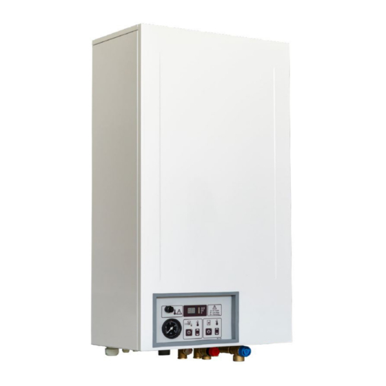
- Page 1 ELECTRIC BOILER FOR CENTRAL HEATING AND WARM WATER PREPARATION THERMO-COMBI USER’S INSTRUCTIONS We reserve the right of changing these instructions without special prior notification TMS-UT-0709-Z07-8...
- Page 2 We reserve the right of changing these instructions without special prior notification...
-
Page 3: Table Of Contents
WE ARE NOT LIABLE FOR DAMAGES RESULTING FROM NON-OBSERVING THESE INSTRUCTIONS Safety information and warnings Read this document carefully before manipulation, any installation, setup, Table of contents or service, and follow the instructions Safety information and warnings ......3 1. Introduction ............1 Keep these instructions in the vicinity of •... -
Page 4: Introduction
1. Introduction 2. About the product THERMO-Combi is the economic boiler for Thank you for the confidence you have shown to us central heating and sanitary water preparation that by having purchased our boiler for central heating and may be used as the independent source of heat. sanitary water preparation. -
Page 5: Integral Parts Of The Thermo-Combi Boiler
2.2. Integral parts of the THERMO-Combi Boiler 1. Central heating primary flow 2. Central heating return flow 3. External shell of the boiler 4. Boiler 5. Thermal insulation 6. Electric heaters 7. Control panel 8. Boots for el. terminals 9. Contactors 10. -
Page 6: Installation
3. Installation 3.1. Important warnings THE GUARANTEE SHALL NOT BE ACCEPTED IF THE FOLLOWING WAS NOT OBSERVED: • THE BOILER SHOULD INTO OPERATION BY THE AUTHORIZED SERVICE, • THE ENCLOSED IMPURITIES COLLECTOR SHOULD BE BUILT IN ON THE STARTING LINE OF CENTRAL HEATING AND INLET COLD SANITARY WATER, •... -
Page 7: Assembly (Continued)
(STB) (6) and PCB with power relays and connectors for pumps, room ‘stat and all probes - (RelBoard) (7). Switchboard for Thermo-Combi 15-24kW Thermo-Combi 28-40kW On the illustration you can see: ground terminal (1), neutral wire terminal (2), operating current trips (3), MCB (miniature circuit breaker) (4), cartridge fuse 6.3A/T for control power (5), cartridge fuse 6.3A/T for... -
Page 8: Power Supply Connection
3.3. Power supply connection Note: Before working on the boiler, turn off the power (e.g. MCB, switches) and secure against accidental switching on. Tightening torque for MCB is 2.0 Nm. A boiler is rated as a high power appliance and fixed wiring must be used. Please observe chapter 2.4. about fuse and conductor requirements. -
Page 9: Connecting Temperature Sensors, Room Thermostat Or External Electrical Controls
3.4. Connecting temperature sensors, room thermostat or external electrical controls 3.4.1. Accessing connection plate In order to access connection plate (2) power connection protection cover (1) must be removed by unwinding two M4 screws and pulling protection cover out. After connecting the power cable, protective cover (1) must be put in place and tightened. -
Page 10: Use Of The Product
4. Use of the product 4.1. Control panel Figure 1 - Control panel “Z” - OPTION Multipurpose – temperature indicator (temperature of Sanitary water temperature adjustment boiler, sanitary water, adjustment of temperature) Push button for switching on and off the sanitary Signalization of operation degree of heaters (1., 2., 3.) water preparation Signalization of boiler operation (green light... -
Page 11: Central Heating Functions
Switching on of domestic water heating By pressing the push button (7), the DHW system is switched on. Upon pressing on the desired water temperature in boiler is displayed for 5 seconds, signalization of DHW operation (8) is twinkling. After 5 seconds the real temperature in the boiler is displayed (1) Adjustment of desired temperature of central heating By pressing the push button for temperature adjustment (6) the desired temperature in the boiler appears, the... -
Page 12: Domestic Water Functions
4.1.2. Domestic water functions Display of desired temperature of domestic water If the key is held pressed less than 5 s the LED display will show the desired temperature in domestic water storage. The value is displayed for 5 seconds, after which the display normally shows the real temperature of water in the boiler. - Page 13 Continuation... Display of current temperature in the domestic water storage By pressing the key down (6) user can select the display of current temperature in the domestic water storage. The value is displayed for 5 s, after which display returns to indication of the actual temperature of water in the boiler..
-
Page 14: Access To Special Service Menu
4.1.3. Access to special service menu Access to special service menu Limiting maximum boiler temperature By pressing the key (4) user can limit maximum boiler temperature. Factory defined maximum temperature starts to blink. By pressing up or down user can set new maximum temperature. -
Page 15: Use Of The Boiler
4.2. Use of the boiler First putting on at the beginning of a season For the first putting on at the beginning of a central heating season, the first step should be to put on the boiler by means of the switch for central heating (5), temperature in the boiler (1) should be adjusted to 30°C (in this was the heaters are disconnected and only circulation pump is in operation). -
Page 16: Manipulation With Automatic Equipment
4.3. Manipulation with automatic equipment Putting on and of the sanitary water preparation The boiler is switched on by means of the main switch (7), for switching on, the switch should be put in the position 1. Upon switching on a desired water temperature in boiler is displayed for 5 seconds, signalization of sanitary water preparation is twinkling (8). - Page 17 Parallel operation of central heating and sanitary water When both modes of operation are active, central heating and sanitary water preparation, the boiler prefers sanitary water. If there is a requirement for warm water, the boiler starts with preparation of sanitary water, the lamp (8) turns on, whereas the boiler operation signalization turns off (3);...
-
Page 18: Recommendations For Optimal Use
4.4. Recommendations for optimal use Central heating For optimal use of the boiler and electric power consumption, we recommend the use of quality room thermostat connected to the boiler. Daily temperature should be between 20°C i 22°C (for each degree above 22°C the consumed energy is increasing exponentially). -
Page 19: Survey Of Possible Defects And Irregularities In Operation
6. Survey of possible defects and irregularities in operation DEFECT CAUSE ELIMINATION - at switching on, no voltage on no feed from net on one or check on serial clamps of the control panel more phases the boiler whether there is fuse 100mA on the control feeding panel blown... - Page 20 - pressure in heating system is defective expansion vessel, if there is water on the valve varying too low or too high pressure for pumping the vessel, in the vessel replace the vessel, pressure in the vessel should be 0,5 – 0,8 bar - RCCB switch is ejecting defective heater, replace the heater,...
-
Page 21: Technical Specification
7. Technical specification Central heating return line Control panel Sanitary water inlet line (cold water) Wall support for suspension Valve for venting the boiler Safety valve at 3 bar Central heating starting line Safety valve at 8 bar Sanitary water outlet line (warm water) Power and room thermostat inlet Filling valve THERMO-Combi Boilers... - Page 22 TABLE OF RECOMMENDED FLOWS Recommended Maximum Power range Minimum flow Optimal flow flow work area [kW] [l/min] [l/min] [l/min] [l/min] 10-35 15-40 15-55 25-70 25-80 30-100 SUPPLY CHARACTERISTICS POWER Nominal Fuse current Rated short-circuit Rated short-circuit Min. conductor's Fuse type RCCB switch type current breaking capacity...
Need help?
Do you have a question about the THERMO-Combi 15 and is the answer not in the manual?
Questions and answers