Table of Contents
Advertisement
Quick Links
Research and Production Enterprise "DISC SYSTEMS" LTD
EDRPOU 16303375, a/c No.260075014037759
at PJSC "UKREXIMBANK" in c. Kyiv
MFO 380333, TIN 163033726585
95-C Otradny Prospekt, Kiev, 03061, Ukraine, phone +38044 507 02 07, fax 038044 507 02 02 www.bitrek.com.ua, sales@bitrek.com.ua
95-C Otradny Prospekt, Kiev, 03061, Ukraine. Phone +38044 507 02 07.
Fax +38044 507 02 02. www.bitrek.com.ua, sales@bitrek.com.ua
Vehicles Tracking Device
BI-810 TREK
Operating Manual
Version 2019.09.1
www.bitrek.com.ua
sales@bitrek.com.ua
+380 44 507 02 07
Advertisement
Table of Contents

Related Manuals for BITREK BI-810 TREK


Summary of Contents for BITREK BI-810 TREK
- Page 1 PJSC "UKREXIMBANK" in c. Kyiv MFO 380333, TIN 163033726585 95-C Otradny Prospekt, Kiev, 03061, Ukraine, phone +38044 507 02 07, fax 038044 507 02 02 www.bitrek.com.ua, sales@bitrek.com.ua 95-C Otradny Prospekt, Kiev, 03061, Ukraine. Phone +38044 507 02 07. Fax +38044 507 02 02. www.bitrek.com.ua, sales@bitrek.com.ua...
-
Page 2: Table Of Contents
Table of Contents Introduction .................... 3 Safety Requirements for Installation and Maintenance of Tracking Device "BI-810 TREK" ................3 Transportation and Storage ..............3 Warranty ..................... 3 Device ....................3 Intended Use of the Device..............3 Principle of Operation ................4 Specifications .................. -
Page 3: Introduction
Device Intended Use of the Device Tracking device BI-810 TREK is used for navigation tasks, remote control and monitoring of a vehicle or other remote object. The tracking device is intended for installation to any mobile or remote stationary object in order to: ... -
Page 4: Principle Of Operation
Data transfer standard 850/900/1800/1900 GPRS, SMS, voice GSM network communication channel communication GPRS grade Navigation system types GPS or GPS/GLONASS GPS and GSM antennas External Auxiliary digital interfaces RS-485 Motion sensor Acceleration meter www.bitrek.com.ua sales@bitrek.com.ua +380 44 507 02 07... -
Page 5: Tracking Device Design
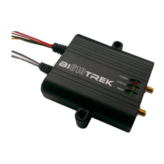
Dimensions (W х L х H) 85 х 95 х 29 mm Weight 175 g Body IP 65 (plastic РА 6) Tracking device design Fig. 1. Appearance and Dimensions of Tracking Device BI-810 TREK. www.bitrek.com.ua sales@bitrek.com.ua +380 44 507 02 07... -
Page 6: Scope Of Delivery
Scope of Delivery 1. Tracking Device BI-810 TREK - 1 pc. 2. GPS antenna – 1 pc. 3. GSM antenna – 1 pc. 4. Certificate – 1 pc. 5. Warranty sheet – 1 pc. 6. Packing box – 1 pc. -
Page 7: Connection Of The Power Supply, Discrete And Analog Sensors, As Well As Extra Devices
Connection of the Power Supply, Discrete and Analog Sensors, as well as Extra Devices Fig. 2. BI-810 TREK Contact Pins Table 2. Pin legends Color Pin legend Signal type Pin purpose "+" on-board power terminal (nominal + Vin Power voltage is 12 VDC or 24... -
Page 8: Installation And Commissioning
Voltage on the discrete inputs and outputs should not exceed 30 V. Voltage on the analog inputs should not exceed 30 V. Device input voltage should not exceed 36 V. Otherwise, the device can be damaged. www.bitrek.com.ua sales@bitrek.com.ua +380 44 507 02 07... -
Page 9: Connection To A Computer
Fig. 3. BI-810 TREK Connection Diagram A terminal program can be used for data exchange with the device. Terminal configuration settings: bit rate – 115,200 bps, data bit – 8, stop bit –... -
Page 10: List Of Sms Commands
1234 getgps; getstatus; ATTENTION! Total length of an SMS command string should not exceed 160 Latin characters. Number of commands per one SMS is only limited by the maximum length of an SMS. www.bitrek.com.ua sales@bitrek.com.ua +380 44 507 02 07... -
Page 11: Configuring The Device
If there is no authorized phone number enabled, SMS with commands will be received from any phone number. Configuring the Device The BI-810 TREK Tracking Device can be configured by one of the methods below: 1. Using a direct connection between the device and a computer. - Page 12 Set a parameter by its ID #### boot #,#,# Update of device firmware Set digital output Out 1 setdigout # operating mode Disabling safety lock with the ignitionoff ignition Enabling safety lock with the ignitionon ignition www.bitrek.com.ua sales@bitrek.com.ua +380 44 507 02 07...
-
Page 13: Detailed Description Of Information Commands
GPS: 1 Sat: 7 Lat: 50.2535 Long: 30.2622 Alt: 147 Speed: 0 Dir: 77 Date: 2018/4/30 Time: 12:33:45 Command of request for link with device coordinates – getmap; Example of a response: "www.biakom.com/maps/q=50.420209,30.428448,12,0" www.bitrek.com.ua sales@bitrek.com.ua +380 44 507 02 07... - Page 14 Command example => request value of ID=0242 parameter: getparam 0242; Parameter Description name Param ID Parameter ID Value Parameter value Example of a response to the "getparam 0242" command: Param ID 0242 Val: internet www.bitrek.com.ua sales@bitrek.com.ua +380 44 507 02 07...
-
Page 15: Detailed Description Of Controlling Commands
PORT – Port of the server containing the update; PATH – Path to the firmware update file on the server; Example of the command: BOOT fw.bitrek.ua,80,*.bin; Where * is a version of the firmware, .bin – file format extension. Options of response to the attempted update download: BOOT: UPDATE DOWNLOAD OK –... -
Page 16: Basic Device Configuration
Once a mobile carrier SIM-card is inserted and power supply is connected, the device needs to be configured for transferring data to the server. When the Bitrek Configurator is used, all configuration settings will be divided into groups: Server and GPRS ... -
Page 17: Configuring I/O Components
SMS with the commands. Configuring I/O Components The BI-810 TREK Tracking Device can collect, process and send data obtained from different sensors to the server. Each sensor is an I/O component and has a group consisting of 6 parameters for configuration. - Page 18 Parameter 2 - Upper threshold – setting the upper threshold of the I/O component; Parameter 3 - Lower threshold – setting the lower threshold of the I/O component; www.bitrek.com.ua sales@bitrek.com.ua +380 44 507 02 07...
- Page 19 Example: Lower threshold of input voltage is set to 0 V, the upper threshold is 10 V (10000 mV). If the input voltage increases over 10 V, the event will be generated (Figure 5). www.bitrek.com.ua sales@bitrek.com.ua +380 44 507 02 07...
- Page 20 5 - Monitoring + Going Beyond Range. When a Going Beyond Range event is generated, actual value from sensor starts www.bitrek.com.ua sales@bitrek.com.ua +380 44 507 02 07...
-
Page 21: Configuring Alarms
SMS messages are sent should be configured as a trigger for outbound SMS messages. A user-defined text may be included with an SMS message, but it should not be more than 30 Latin www.bitrek.com.ua sales@bitrek.com.ua +380 44 507 02 07... -
Page 22: Description Of Operator Selection Modes
Select respective mode: setparam 0917 1; APN, Usname, Uspass should be unfilled: setparam 0242 < >; setparam 0243 < >; setparam 0244 < >; www.bitrek.com.ua sales@bitrek.com.ua +380 44 507 02 07... -
Page 23: Configuring The Device For Operation With Rfid Readers
Configuring the Device for Operation with RFID Readers The BI-810 TREK Tracking Device is compatible with RFID readers via the RS-485 bus. To configure the reader correctly, please, read its manual carefully first. -
Page 24: Configuring The Device For Operation With Fuel Meter Rs-485
Configuring the Device for Operation with Fuel Meter RS-485 The BI-810 TREK Tracking Device is compatible with fuel meter supporting RS-485 bus. In total, up to four fuel meters can be connected. Respective I/O component must be enabled in the configuration settings of the device. -
Page 25: Use Of Backup Server
Fig. 8. А & В Communication Line Connection and Configuration Diagram. Use of Backup Server The BI-810 TREK Tracking Device supports the use of a backup server (Host2 Port2). The ID=196 parameter is used for this case and by default is set to 0. - Page 26 When the lock is disabled, the device will send the response: ignitionoff; ATTENTION! The ignitionon; ignitionoff; commands will be performed by the device provided that they have been received via SMS message. www.bitrek.com.ua sales@bitrek.com.ua +380 44 507 02 07...
-
Page 27: Addendum 1. Device Parameters
Connect Try Time between connection 0905 none 2 byte sec. 0 - 65535 Interval attempts Connect Time between serial Serial 0906 none 2 byte sec. 0 - 65535 attempts to connect Interval www.bitrek.com.ua sales@bitrek.com.ua +380 44 507 02 07... - Page 28 1 - 180 azimuth Record Number of records per 0232 none 2 byte pcs. 0 - 65535 Amount packet Acceleration meter X- Delta X 0281 none 1 byte c.u. 1 - 256 direction deviation angle www.bitrek.com.ua sales@bitrek.com.ua +380 44 507 02 07...
- Page 29 GPS for movement km/h 1 - 256 speed detection 0 or 3 - GPS+GLONASS; GPS Source Selecting geopositioning 4016 none 1 byte c.u. 1 - GPS only; Select system 2 - GLONASS only; www.bitrek.com.ua sales@bitrek.com.ua +380 44 507 02 07...
- Page 30 0252 none String SMS access login Login 0253 none String SMS access password Password Password Terminal 0910 none String Device access password 11111 Password Enabling SIM-card carrier's SIM_PIN 0818 none 1 byte PIN-number www.bitrek.com.ua sales@bitrek.com.ua +380 44 507 02 07...
- Page 31 (digital 0994 none 1 byte Trigger with digital inputs input) used for response to incoming call Number of rings prior to RingNum 0912 none 1 byte pcs. 1 - 256 auto phone pickup www.bitrek.com.ua sales@bitrek.com.ua +380 44 507 02 07...
- Page 32 Text added to SMS (NMT 30 SMSText 0817 none String Text Latin characters) Roaming Operator 0 – disabled; 1 - Selection 0917 none 1 byte Enabling carrier selection enabled Enable www.bitrek.com.ua sales@bitrek.com.ua +380 44 507 02 07...
- Page 33 (X+1) AIN1_filter Period of data retrieval by 0959 none 2 byte *50m period AIN1 median filtering (X+1) AIN2_filter Period of data retrieval by 0980 none 2 byte *50m period AIN2 median filtering www.bitrek.com.ua sales@bitrek.com.ua +380 44 507 02 07...
- Page 34 Polling period for RS485 period_RFID 0201 none 2 byte RFID RKS (SOVA) sec. _RKS FactorF 0950 none 4 byte F factor for Kalman filter c.u. 1000000 www.bitrek.com.ua sales@bitrek.com.ua +380 44 507 02 07...
- Page 35 GSM_Reg Timeout for registration on 4019 none 2 byte 60 – 300 Timeout the GSM network GPRS_Reg Timeout for registration on 4020 none 2 byte 60 - 300 Timeout the GPRS network www.bitrek.com.ua sales@bitrek.com.ua +380 44 507 02 07...
- Page 36 9): control. 13 - controlling DOUT1 RFID (network address 10): 17 - controlling DOUT1 RadioMod Enabling wireless sensor of 0 – disabled; 1 - 0808 none 1 byte none tailing equipment enabled www.bitrek.com.ua sales@bitrek.com.ua +380 44 507 02 07...
-
Page 37: Addendum 2. List Of I/O Components
0425 0410… 2 byte Power supply voltage 0415 0490… GPSSpeed 2 byte Speed per GPS km/h 0495 0450… 0 – disabled, 1 – GPSPower 1 byte Availability of GPS signal pcs. 0455 enabled www.bitrek.com.ua sales@bitrek.com.ua +380 44 507 02 07... - Page 38 0695 meter (network address 1) fuelLevel 0700… Polling non-filtered fuel 2 byte c.u. Unfilt2 0705 meter (network address 2) fuelLevel 0870… Polling non-filtered fuel 2 byte c.u. Unfilt5 0875 meter (network address 5) www.bitrek.com.ua sales@bitrek.com.ua +380 44 507 02 07...
- Page 39 0535 meter (network address 6) 0680… Transmission of carrier's OperCode 4 byte none 0685 code 0750… Transmission of device 0 - not active; modemStat 1 byte none 0755 modem status 1 - active; www.bitrek.com.ua sales@bitrek.com.ua +380 44 507 02 07...
- Page 40 1 - home network; 2 - not registered, 0760… GSM network registration but searching for GSM_Stat 1 byte none 0765 status carriers; 3 - registration disabled; 4 - status unknown; 5 - roaming; www.bitrek.com.ua sales@bitrek.com.ua +380 44 507 02 07...
- Page 41 Frequency input count_dLow 0830… 4 byte (transmission of number of c.u. 0835 pulses per 5 sec, dlow1) Instantaneous pulse 0320… fast_dlLow1 4 byte counter (Upper bandwidth c.u. 0325 limit up to 20 kHz, dlow1) www.bitrek.com.ua sales@bitrek.com.ua +380 44 507 02 07...
- Page 42 8 byte none 0625 address 3) RFID_ 3800… RFID RKS identifier (SОVА) 8 byte none RKS_9 3805 (network address 9) RFID_ 3830.. RFID RKS identifier (SОVА) 8 byte none RKS_10 3835 (network address 10) www.bitrek.com.ua sales@bitrek.com.ua +380 44 507 02 07...
- Page 43 0 - 255 0735 elevation angle 0740… Actual value of Z-direction axesZ 1 byte degrees 0 - 255 0745 elevation angle 0800… Horizontal accuracy HDOP 2 byte c.u. 0 - 9999 0805 determination www.bitrek.com.ua sales@bitrek.com.ua +380 44 507 02 07...
- Page 44 Date Version Note 12.06.2018 Ver.2018.06.1 Basic document 09.07.2018 Ver.2018.07.1 Changed the firmware update port number 09.10.2018 Ver.2018.10.1 Added new I/O element IDconf 0907 02.09.2019 Ver.2019.09.1 Added description of ID_Send 136, 137, 159, 76 www.bitrek.com.ua sales@bitrek.com.ua +380 44 507 02 07...
Need help?
Do you have a question about the BI-810 TREK and is the answer not in the manual?
Questions and answers