Table of Contents
Advertisement
Quick Links
Advertisement
Chapters
Table of Contents

Related Manuals for Beckhoff C6915


Summary of Contents for Beckhoff C6915
- Page 1 Manual | EN C6915 Industrial PC 2024-04-03 | Version: 3.1...
-
Page 3: Table Of Contents
Grounding of the Industrial PC.................. 23 4.3.3 Connecting cables and power supply ................ 24 Switching the Industrial PC on and off .................... 26 5 Beckhoff Device Manager ........................ 28 6 Decommissioning ........................... 30 Disconnecting the power supply and cables ................... 30 Disassembly and disposal....................... 31 7 Maintenance ............................ 32... - Page 4 Table of contents Version: 3.1 C6915...
-
Page 5: Notes On The Documentation
EP1590927, EP1789857, EP1456722, EP2137893, DE102015105702 and similar applications and registrations in several other countries. ® EtherCAT is registered trademark and patented technology, licensed by Beckhoff Automation GmbH, Germany Copyright © Beckhoff Automation GmbH & Co. KG, Germany. The distribution and reproduction of this document as well as the use and communication of its contents without express authorization are prohibited. -
Page 6: For Your Safety
Exclusion of liability Beckhoff shall not be liable in the event of non-compliance with this documentation and thus the use of the devices outside the documented operating conditions. -
Page 7: Fundamental Safety Instructions
• the operating instructions are in good condition and complete, and always available for reference at the location where the products are used. C6915 Version: 3.1... -
Page 8: Notes On Information Security
For your safety Notes on information security The products of Beckhoff Automation GmbH & Co. KG (Beckhoff), insofar as they can be accessed online, are equipped with security functions that support the secure operation of plants, systems, machines and networks. Despite the security functions, the creation, implementation and constant updating of a holistic security concept for the operation are necessary to protect the respective plant, system, machine and networks against cyber threats. -
Page 9: Product Overview
Product overview Product overview The C6915 Industrial PC belongs to the series of compact Industrial PCs for space-saving control cabinet installation. The device is suitable for various applications and requirements. Thanks to the available processors, the Industrial PC can be used for the following applications, among others: •... -
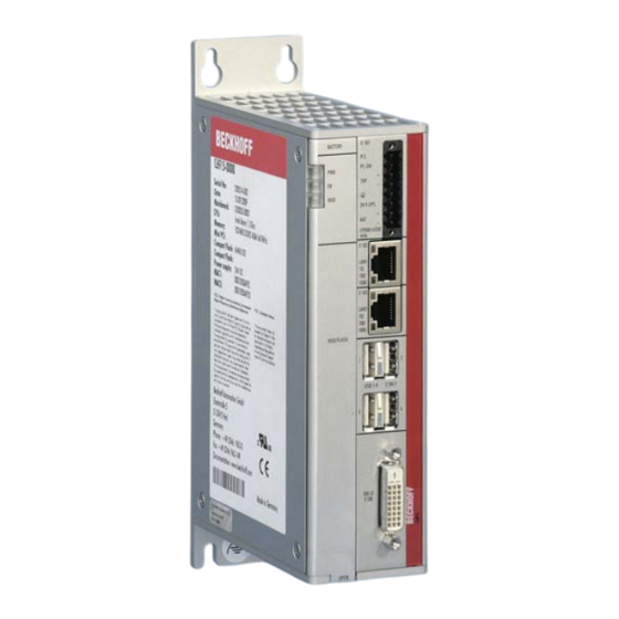
Page 10: Structure
Product overview Structure Fig. 1: Structure Table 1: Key: C6915 structure Component Description Mounting plate Plate for mounting the Industrial PC by its the rear side in the control cabinet Name plate Information on the equipment of the Industrial PC Status LEDs... -
Page 11: Interface Description
Product overview Interface description The basic version of the C6915 has the following interfaces: • Power supply (X101) • Ethernet RJ45 (X102, X103) • USB (X104 - X107) • DVI (X108) 3.2.1 Power supply The industrial PC is supplied with a nominal voltage of 24 V. The 8-pin voltage socket (X101) is used for connection to the power supply and the external wiring of the industrial PC. -
Page 12: Ethernet Rj45
Product overview 3.2.2 Ethernet RJ45 The C6915 has two Gigabit LAN ports (X102, X103). The 100Base-T and 1000Base-T Ethernet standards enable the connection of corresponding network components and data rates of 100/1000 Mbit/s. The required speed is selected automatically. The RJ45 connection technology with twisted-pair cables is used. The maximum length of the cable connection is 100 m. -
Page 13: Usb
USB interfaces. The following table shows the interface assignment based on the device generation: Table 5: USB interfaces based on device generation Generation USB interfaces C6915-0010 4x USB 2.0 C6915-0020 2x USB 3.0 2x USB 2.0 Each of the four USB interfaces supplies up to 500 mA current and is electronically fused. -
Page 14: Dvi
DDC Clock + 5 V Power TMDS Clock Shield DDC Data Ground (+ 5 V, Analog H/ TMDS Clock + V Sync) Analog Vertical Sync Hot Plug Detect TMDA Clock - Version: 3.1 C6915... -
Page 15: Status Leds
Color/flashing interval Meaning PWR (Power) green Computer on Computer off FB (fieldbus) TwinCAT Stop blue TwinCAT Config blue/red flashing TwinCAT Config (fieldbus error) green TwinCAT Run green/red flashing TwinCAT Run (fieldbus error) HDD (hard disk) Accessing storage media C6915 Version: 3.1... -
Page 16: Name Plate
The name plate provides information on the equipment fitted to the industrial PC. The name plate shown here serves only as an example. xxxxxxxx xxxxxxxxxxxxx xxxxxxxxxxxxx Fig. 7: Name plate example Table 9: Legend C6915 name plate Description Model: the last four digits indicate the device generation. Serial number (BTN) Date of manufacture Mainboard... -
Page 17: Commissioning
3. Check your delivery for completeness by comparing it with your order. 4. Check the contents for visible shipping damage. 5. In case of discrepancies between the package contents and the order, or in case of transport damage, please inform Beckhoff Service (see Chapter 10.1 Service and support). C6915 Version: 3.1... -
Page 18: Installation In The Control Cabinet
• Mount the device only in the orientations shown in the documents. The C6915 Industrial PC is designed for mounting in control cabinets in machine and plant engineering applications. Please observe the environmental conditions prescribed for the operation (see Chapter 9 Technical data [} 39]). -
Page 19: Dimensions
Figure 9 shows the dimensions of the industrial PC with mounting plate 1. 120,3 124,3 Fig. 9: Dimensions of mounting plate 1 Figure 10 shows the dimensions of the industrial PC with mounting plate 2. 95,2 120,3 Fig. 10: Dimensions of mounting plate 2 C6915 Version: 3.1... -
Page 20: Installation In The Control Cabinet
1. Place the fastening screws in the drill holes in the rear panel of the control cabinet. 2. Hang the PC on the screws at the marked points of the mounting plate (see Fig. 11). 3. Tighten the fastening screws. ð You have successfully installed the industrial PC in the control cabinet. Version: 3.1 C6915... -
Page 21: Connecting The Industrial Pc
Wire the industrial PC in the control cabinet in accordance with the EN 60204-1:2006 standard on Protective Extra Low Voltage (PELV) so that one side of the circuit or a point on the power source of this circuit is connected to the protective conductor system. C6915 Version: 3.1... -
Page 22: Installing The Supply Cable
3. Tighten the cable tie and remove the plastic tab (section C). 4. Attach the upper part of the strain relief housing by snapping it onto the lower part (section D). Fig. 12: Assembly of strain relief housing Version: 3.1 C6915... -
Page 23: Grounding Of The Industrial Pc
The functional earth is necessary for the EMC of the device. The functional earth is established by connecting the grounding point on the PC mounting plate to the central grounding point of the control cabinet in which the PC is installed. C6915 Version: 3.1... -
Page 24: Connecting Cables And Power Supply
If you ordered your device with an integrated UPS, then you can connect an external battery pack and install it on a DIN rail near to the PC. Use only Beckhoff battery packs for this: • C9900-U330: universal battery pack for PCs and panel PCs in any configuration •... -
Page 25: Fig. 13 Wiring Diagram
The maximum load is 1.4 A (max. 2.5 A from year of manufacture 2016). Once the PC has been de-energized via the UPS software, the UPS output is switched to 0 V. A connected panel is switched off. C6915 Version: 3.1... -
Page 26: Switching The Industrial Pc On And Off
When you switch on the PC for the first time, the optionally pre-installed operating system will be started. For any additional hardware you have connected, you have to install the drivers yourself afterwards. In addition, the Beckhoff Device Manager starts automatically. The Device Manager is a software from Beckhoff that supports you in configuring the PC. -
Page 27: Table 10 Ups Communication
Communication via BIOS API In the case of serial communication, all you need is the UPS driver. If the communication takes place via the BIOS API, you also need the Beckhoff Automation Device Driver in addition to the UPS driver. C6915... -
Page 28: Beckhoff Device Manager
• User name: Administrator • Password: 1 You also have the option of using the Beckhoff Device Manager to remotely configure the industrial PC via a web browser. More detailed information is available in the Beckhoff Device Manager manual. First start Beckhoff Device Manager When your industrial PC is booted for the first time, the Beckhoff Device Manager also starts automatically for the first time. -
Page 29: Fig. 15 Beckhoff Device Manager - Start Page
Secure passwords Strong passwords are an important prerequisite for a secure system. Beckhoff supplies the device images with standard user names and standard passwords for the operating system. It is imperative that you change these. Controllers are shipped without a password in the UEFI/BIOS setup. Beckhoff recommends assigning a password here as well. -
Page 30: Decommissioning
5. Make a note of the wiring of all data transmission cables if you want to restore the cabling with another device. 6. Disconnect the data transmission cables from the industrial PC. 7. Finally, disconnect the grounding strap. ð You have disconnected the cables and the power supply. Version: 3.1 C6915... -
Page 31: Disassembly And Disposal
• Electronic parts such as fans and circuit boards must be disposed of in accordance with national electronic scrap regulations. • Stick insulating tape over the poles of the CR2032 battery on the motherboard and dispose of the battery via the local battery recycling. C6915 Version: 3.1... -
Page 32: Maintenance
Maintenance measures increase the efficiency of the device by ensuring long-term functionality. Cleaning and maintenance by replacing certain device components contribute to this. Repair Only the vendor may repair the device. If a repair should be necessary, contact Beckhoff Service (see Chapter 10.1 Service and Support [} 40]). Cleaning... -
Page 33: Table 11 Device Component Replacement Recommendations
NOTICE Use of incorrect spare parts The use of spare parts not ordered from Beckhoff Service can lead to unsafe and faulty operation. • Only use spare parts that you have ordered from Beckhoff Service. Beckhoff devices are manufactured from components of the highest quality and robustness. They are selected and tested for best interoperability, long-term availability and reliable function under the specified environmental conditions. - Page 34 • Only remove new electronic components from the ESD packaging (tinted plastic bag) after putting on the wrist grounding strap. • Do not walk around with electronic components in your hand if they are not in ESD packaging. Version: 3.1 C6915...
-
Page 35: Access To Device Components
To access the battery and the storage media, open the front flap (see Fig. 17). Fig. 17: Tool-free access to battery and storage media You now have access to the battery (1) and storage media (2) (see fig. 18). Fig. 18: Battery and storage media C6915 Version: 3.1... -
Page 36: Replacing The Battery
Replace battery with R/C (BBCV2), Part. No. CR2032, rated 3 V only. Use of another battery may present a risk of fire or explosion. • Only replace the battery with a replacement battery from Beckhoff Service. • When replacing the battery, make sure that the polarity is correct. -
Page 37: Replacing The Storage Media
If you want to exchange a storage medium according to Beckhoff's recommendation, you must copy the data from the old to the new storage medium. You can use the Beckhoff Service Tool (BST) for this purpose. BST is a graphical backup and restore program for PCs with a Windows operating system. You can create an image of your operating system and use it to back up the operating system. -
Page 38: Troubleshooting
Measures No function of the industrial PC Missing power supply of the Check the power supply cable industrial PC Call Beckhoff Service Other cause The industrial PC does not boot BIOS setup settings are incorrect Check BIOS setup settings (load... -
Page 39: Technical Data
Technical data Technical data Table 13: Technical data Product designation C6915 Dimensions (W x H x D) 48 x 164 x 119 mm, without mounting plate Weight 1250 g with basic configuration Supply voltage 22-30 V DC (24 V DC power supply unit) NEC Class 2... -
Page 40: 10 Appendix
33415 Verl Germany Phone: + 49 5246/963-0 email: info@beckhoff.de The addresses of the worldwide Beckhoff branches and agencies can be found on our website at http:// www.beckhoff.com/. You will also find further documentation for Beckhoff components there. Version: 3.1 C6915... -
Page 41: Approvals
FCC approvals for Canada FCC: Canadian Notice This device does not exceed the class A limits for radiation, as specified by the Radio Interference Regulations of the Canadian Department of Communications. C6915 Version: 3.1... - Page 42 Fig. 12 Assembly of strain relief housing ....................Fig. 13 Wiring diagram ..........................Fig. 14 Beckhoff Device Manager - Change passwords ................Fig. 15 Beckhoff Device Manager – Start page ..................Fig. 16 Dismantling the control cabinet ....................Fig. 17 Tool-free access to battery and storage media................
- Page 43 List of tables List of tables Table 1 Key: C6915 structure ........................Table 2 Voltage socket pin assignment ....................Table 3 Controller classification based on device generations ..............Table 4 Ethernet interface pin assignment....................Table 5 USB interfaces based on device generation ................
- Page 45 More Information: www.beckhoff.com/C6915/ Beckhoff Automation GmbH & Co. KG Hülshorstweg 20 33415 Verl Germany Phone: +49 5246 9630 info@beckhoff.com www.beckhoff.com...
Need help?
Do you have a question about the C6915 and is the answer not in the manual?
Questions and answers