
Subscribe to Our Youtube Channel
Related Manuals for Viega Grundfix Plus


Summary of Contents for Viega Grundfix Plus
- Page 1 Instructions for Use Grundfix Plus Control backflow trap type 3 for wastewater pipe containing faeces Model Year built (from) 4987.41 01/2010...
-
Page 2: Table Of Contents
Operating condition - normal operation 3.4.3 Operating condition – back pressure 3.4.4 Operating condition – malfunction 3.4.5 Operating condition – battery-powered emer‐ gency operation 3.5 Errors, faults and remedy 3.6 Care and maintenance Grundfix Plus Control backflow trap type 3... - Page 3 Table of contents 3.6.1 Inspection 3.6.2 Maintenance 3.6.3 Replacing the rechargeable battery 3.7 Disposal Grundfix Plus Control backflow trap type 3...
-
Page 4: About These Instructions For Use
This restriction does not extend to possible operating instructions. The installation of Viega products must take place in accordance with the general rules of engineering and the Viega instructions for use. -
Page 5: About This Translated Version
German/European directives specified in this manual: The information herein is not binding for other countries and regions; as said above, they should be understood as a recommendation. Grundfix Plus Control backflow trap type 3... -
Page 6: Product Information
Regulations from section: Disposal Scope / Notice Regulations applicable in Ger‐ many Disposal of electronic compo‐ WEEE-Richtlinie 2012/19/EU nents Regulations from section: Inspection Scope / Notice Regulations applicable in Ger‐ many Monthly inspection DIN 1986-3 Grundfix Plus Control backflow trap type 3... -
Page 7: Safety Advice
2.3.1 Areas of use The Grundfix Plus Control is operated electrically. It is suitable for use in drain pipelines with household-type wastewater carrying faecal matter (up to a temperature of 95 °C with pH values of ≥ 4 or ≤ 10). -
Page 8: Place Of Installation And Installation Conditions
WC at their disposal above the back pressure level which they could use in case of a backflow at the drainage point. Fig. 1: Wrong place of installation of the backflow trap Grundfix Plus Control backflow trap type 3... - Page 9 Product information Fig. 2: Correct place of installation of the backflow trap Street = Backflow level Area safe from backflow Grundfix Plus Control backflow trap type 3...
-
Page 10: Maintenance
A monthly inspection must be carried out to ensure safe operation. See Ä Chapter 3.6.1 ‘Inspection’ on page 33 Maintenance must be carried out twice a year to ensure safe operation. Ä Chapter 3.6.2 ‘Maintenance’ on page 34 Grundfix Plus Control backflow trap type 3... -
Page 11: Product Description
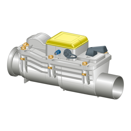
Product information Product description 2.4.1 Overview Fig. 3: Components of the backflow trap Measuring funnel Pressure hose connection cable control Motor Pressure switch Emergency lock actuation Casing Emergency lock shutter 10 - Motor-powered flap Grundfix Plus Control backflow trap type 3... -
Page 12: Technical Data
RTC real time clock power reserve 30 days rechargeable battery 12 V 1.2 Ah integrated charge and test elec‐ tronics for battery operation for up to 24 hours in the case of power failure Grundfix Plus Control backflow trap type 3... -
Page 13: Operating Mode
230 V mains power supply fails. Using the manual actuator, the backflow trap can be closed manually and independently of the motor-powered flap. 2.4.4 Control elements Fig. 5: Control elements backflow trap 1 - Emergency shut-off Grundfix Plus Control backflow trap type 3... - Page 14 Product information Fig. 6: Control elements control unit 1 - Menu T1 2 - Test T2 3 - Reset T3 Grundfix Plus Control backflow trap type 3...
-
Page 15: Handling
If a backflow trap is retro-fitted in a base pipeline, the height difference of 30 mm between connection pipe and sleeve must be taken into account. Grundfix Plus Control backflow trap type 3... -
Page 16: Assembly
Close the empty pipe at both sides using plugs. 3.2.2 Connecting connection cable and pressure hose Do not loosen factory-fitted threaded cable and hose screw fittings on the casing. Otherwise, the anti-flooding function cannot be ensured. Grundfix Plus Control backflow trap type 3... - Page 17 Tighten the union nut of the pressure hose slightly using tools. Connecting connection cable ▶ Remove the closing cap. ▶ Plug in the electric plug connection straight. NOTICE! Make sure that the plug is plugged in straight. Grundfix Plus Control backflow trap type 3...
-
Page 18: Connecting The Control
An electric shock can lead to burns and serious injury and even death. Only allow electrical work to be carried out by spe‐ cialist companies. Remove mains plug before opening the casing. ▶ Attach the control unit onto the wall with 4 screws. Grundfix Plus Control backflow trap type 3... - Page 19 Connect the pressure hose to the control using the quick connec‐ tion. ▶ Lead the connection cable via the PG screw fitting into the internal space of the control. Attach the cable ends: ▶ black: - red: + ▶ Insert the rechargeable battery. Grundfix Plus Control backflow trap type 3...
- Page 20 Yellow motor connec‐ motor + tion signalises RÜCK (BACK) back flow signalises RÜCK (BACK) back flow signalises fault STÖR (FAULT) signalises fault STÖR (FAULT) brown Pressure Sensor switch White Pressure Sensor switch Grundfix Plus Control backflow trap type 3...
- Page 21 An incorrect jumper position can lead to malfunctions. Back flow protection is no longer ensured. ▶ When using the cable set (20 m, art.-no. 483 500), place jumpers onto both contacts (see illustration). Grundfix Plus Control backflow trap type 3...
-
Page 22: Commissioning
Date and time must be set after the initial commissioning, as a prerequisite that the maintenance reminder, error log‐ ging and daily self-test can function. Ä Chapter 3.4.2 ‘Operating condition - normal operation’ on page 26 Grundfix Plus Control backflow trap type 3... -
Page 23: Pressure Test
Set the emergency lock in "ZU" (OFF) position. ▶ ▶ Close the motor-powered flap by pressing the button T2. ▷ Display: [Test NRV closed] ▶ Unscrew the brass plug from the lid. ▶ Screw in the test funnel. Grundfix Plus Control backflow trap type 3... - Page 24 Open the motor-powered flap by pressing button T2. ▶ Remove the test funnel. ▶ Screw in the brass plug. ▷ The control automatically changes back to normal operation after a successful procedure. Display: [Normal operation / NRV opened] Grundfix Plus Control backflow trap type 3...
-
Page 25: Control
29 [Back pressure] Suggestion to close Continuous signal Operating condition – back emergency lock pressure [Close emergency lock] Risk of flooding! Ä Chapter 3.4.3 ‘Operating condition – back pressure’ on page 29 Grundfix Plus Control backflow trap type 3... -
Page 26: Operating Condition - Normal Operation
With the T3 button, you can access a menu and save and exit the menu after selected a suitable value. Within the menus, you can scroll up and down through the values with the T1 and T2 buttons. Grundfix Plus Control backflow trap type 3... - Page 27 [Normal Menu display operation ] starts at the beginning [NRV opened] [Normal Press once Test NRV operation ] closed Test backflow trap closes Grundfix Plus Control backflow trap type 3...
- Page 28 When the memory is full, the oldest event is overwritten. The following events are displayed: Display Meaning [Re-init] Reset or initialisation of the control unit [Motor fault] Motor fault [Maintenance completed] Successful maintenance [Date adjustment] Changing of the date Grundfix Plus Control backflow trap type 3...
-
Page 29: Operating Condition - Back Pressure
[Normal operation] . 3.4.4 Operating condition – malfunction Mechanical faults or errors around the control are shown on the display and an acoustic alarm sounds. During an error, the following functions can be carried out: Grundfix Plus Control backflow trap type 3... -
Page 30: Operating Condition - Battery-Powered Emergency Operation
The following functions can be performed during emergency battery operation: Button Function Menu display Reset with opening and closing of the motor-powered flap Maintenance works are not possible during battery opera‐ tion. Grundfix Plus Control backflow trap type 3... -
Page 31: Errors, Faults And Remedy
– the relevant error messages are shown on the display. NOTICE! To avoid damage to the mechanism, button functions should only be used if the cover is firmly screwed to the Grundfix Plus-Control. Grundfix Plus Control backflow trap type 3... - Page 32 Motor-powered flap trol unit. If the error blocked message remains, replace cover (model 4987.418) The components integrated into the cover cannot be replaced individually. Grundfix Plus Control backflow trap type 3...
-
Page 33: Care And Maintenance
To ensure safe operation, a monthly inspection must be carried out by a professional, see Ä ‘Regulations from section: Inspection’ on page 6. Check the functions of the Grundfix Plus-Control: ▶ Close and re-open the motor-powered flap by pressing the button T2. - Page 34 When using cameras and cleaning devices (cleaning spiral, high- pressure cleaner), protect the backflow trap against mechanical damage. Only begin maintenance after ensuring that no backflow situation exists and the drainage objects in front of the backflow trap are not used. Grundfix Plus Control backflow trap type 3...
- Page 35 [Sound off] and T3. The display goes off after the maintenance has completed. There is a pressure switch in the lid of the Grundfix Plus Control which issues the signal to close the motor-powered flap in case of back pres‐...
- Page 36 Carefully clean the opening for the pressure switch on the lower side of the cover with a small brush. ▶ Take out and clean the flaps. ▶ Check seals, if necessary, replace them. Grundfix Plus Control backflow trap type 3...
- Page 37 ▶ Install the flaps. ▶ Place the lid on and screw it down. ▶ Open the motor-powered flap by pressing button T2. ▶ Actuate the emergency lock and check it for smooth function. Grundfix Plus Control backflow trap type 3...
- Page 38 Keep the water level in the test funnel constant for 10 minutes by replenishing. Observe loss. If the loss is greater than 0.5 l, check and, if required, replace ▷ the seals on the flaps. Grundfix Plus Control backflow trap type 3...
- Page 39 Remove mains plug before opening the casing. If the rechargeable battery is faulty, it must be replaced. This will be shown on the display using the notice [Battery error / Replace battery] . Grundfix Plus Control backflow trap type 3...
- Page 40 Insert the replacement battery fuse (right) comprised in the delivery. The charging time begins approx. 30 seconds after the ▷ rechargeable battery fuse has been inserted. The green LED on the inside of the lid is lit Display indication: [Battery charging] Grundfix Plus Control backflow trap type 3...
- Page 41 Electronic components and batteries must not be put in the domestic waste but must be disposed of appropriately in conformity with the applicable directives, see Ä ‘Regulations from section: Disposal’ on page 6. Grundfix Plus Control backflow trap type 3...
- Page 42 Viega GmbH & Co. KG service-technik@viega.de viega.com INT • 2021-11 • VPN210611...
Need help?
Do you have a question about the Grundfix Plus and is the answer not in the manual?
Questions and answers