Table of Contents
Advertisement
Quick Links
c-pro 3 OEM
Hardware manual:
Programmable controls
114CP3OEE104
Applications
Refrigeration
units
|
Flexible, modular, expandable
|
21 inputs and outputs
|
Variety of communications ports
|
Models with management of Pulse electronic
expansion valves
|
Models with integrates user interface or in blind
version
|
Standard 8 DIN module format
|
OEM oriented
EVCO | 06.08.2021 | AZ
Chiller
Display
cabinets
| 1
Advertisement
Table of Contents

Related Manuals for Evco c-pro 3 OEM


Summary of Contents for Evco c-pro 3 OEM
- Page 1 21 inputs and outputs Hardware manual: Variety of communications ports Programmable controls Models with management of Pulse electronic expansion valves Models with integrates user interface or in blind version Standard 8 DIN module format OEM oriented 114CP3OEE104 EVCO | 06.08.2021 | AZ...
- Page 2 3 OEM - Hardware manual IMPORTANT Read this document thoroughly before installation and before use of the device and follow all recommendations; keep this document with the device for future consultation. Only use the device in the way described in this document; do not use the same as a safety device...
- Page 3 3 OEM - Hardware manual Index | Introduction | Purchasing codes |Open frame version | Purchasing codes |Plastic housing version (blind/LCD) | Dimensions |Open frame version |Plastic housing version (blind) |Plastic housing version (LCD) | Installation |Open frame version...
-
Page 4: Table Of Contents
| Housing and blind version configuration |Through a controller with user interface |Configuration |Switching ON/OFF the device |Accessing the procedure from c-pro 3 OEM LCD |CAN node address setting |Accessing the menu from c-pro 3 OEM LCD |Parameters configuration from c-pro 3 OEM LCD... - Page 5 3 OEM - Hardware manual | Accessories |Connection cables |0810500018/0810500020 |USB flash drive |EVUSB4096M |RS-485/USB serial interface |EVIF20SUXI |INTRABUS/RS-485 serial interface |EVIF22ISX |Phase cutting speed regulator |EVDFAN1 |Connection kit |CJAV45 | Technical data 114CP3OEE104 EVCO | 06.08.2021 | AZ...
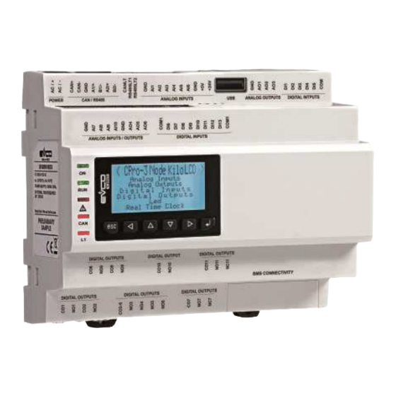
- Page 6 3 OEM - Hardware manual Introduction c-pro 3 OEM is a range of programmable controllers in 8-DIN modules, open-board or with housing (blind or with built-in LCD display). It has numerous inputs and outputs (up to 21) and an enhanced memory capacity to meet the management needs of the HVAC/R sector and OEM companies in particular.
- Page 7 3 OEM - Hardware manual Purchasing codes Open frame version The following table shows the available c-pro 3 OEM models, open frame version, and the relative purchasing codes Models Features EPB90 EPB90R EPB90V Power supply 115... 230 VAC •...
- Page 8 3 OEM - Hardware manual Purchasing codes Plastic housing version (blind/LCD) The following table shows the available c-pro 3 OEM models, plastic housing version (blind/LCD), and the relative purchasing codes Models Features EPB9BXE EPB9BRE EPB9BVE EPB9DRE Power supply 115... 230 VAC •...
- Page 9 3 OEM - Hardware manual Dimensions Open frame version 31 mm (1 142 mm (5 ⁄ ⁄ Plastic housing version (blind) 60 mm (2 ⁄ 142 mm (5 ⁄ Plastic housing version (LCD) 004_c-pro3OEM_Giorno_DIN_001_0.1_AZ 60 mm (2 ⁄ 142 mm (5 ⁄...
- Page 10 3 OEM - Hardware manual Installation Open frame version 1. To install the device : – operate as shown in pictures 1 and 2 1. To uninstall the device: – operate as shown in pictures 3 and 4 2. To install the device again: –...
- Page 11 Disconnect the power supply before doing any type of maintenance – Do not use the device as safety device – For repairs and for further informations, contact the EVCO sales network; possible returns without label data will not be accepted Connectors description Open frame version...
- Page 12 3 OEM - Hardware manual Connector 5 Connector 6 Number Description Number Description Device power supply (115... 230 VAC) INTRABUS port data Device power supply (115... 230 VAC) Reference (GND) If present, signal + RS-485 MODBUS master/slave port If present, signal - RS-485 MODBUS master/slave...
- Page 13 3 OEM - Hardware manual Plastic housing version (blind/LCD) Connector 8 Connector 6 AO4 AO3 AO2 AO1 D14 D13 IN1 GND 12VS CAN+ CAN- Connector 7 c-pro 3 OEM Connector 9 DIHV5 DIHV5 Pulse - EPB9BVE Connettore 10 Connector 3...
- Page 14 3 OEM - Hardware manual Connector 7 Connector 8 Number Description Number Description USB port, for device programming Analogue output 4 (for 0-10 V or PWM) Analogue output 3 (for 0-10 V or PWM) Analogue output 2 (for 0-10 V or PWM)
- Page 15 3 OEM - Hardware manual Electrical connection Open frame version PC with Device UNI- with PRO 3 INTRABUS Device with CAN port Mains supply (115... 230 VAC) INTRA cable + + + AO4 AO3 AO2 AO1 M9 M1 GND 12V...
- Page 16 3 OEM - Hardware manual Plastic housing version (blind/LCD) PC with Device UNI- with PRO 3 INTRABUS Device with CAN port Mains supply (115... 230 VAC) INTRA cable + + + AO4 AO3 AO2 AO1 D14 D13 IN7 IN1 GND 12VS...
- Page 17 3 OEM - Hardware manual User interface version configuration Keyboard Key description Keys Instructions LEFT AND RIGHT UP AND DOWN ENTER Switching ON/OFF the device Progression Description Connect the power supply: it will be started an internal test that takes...
-
Page 18: Housing And Blind Version Configuration
Configuration The following procedures show an example of how to configure a blind programmable controller through a programmable controller with user interface (in the example c-pro 3 OEM LCD): 1. Disconnect the controllers power supply 2. Connect the blind controller to the controller with user interface through the CAN CANBUS port 3. -
Page 19: Accessing The Menu From C-Pro 3 Oem Lcd
3 OEM - Hardware manual Accessing the menu from c-pro 3 OEM LCD Instructions Touch UP and DOWN keys for 2 seconds: the display will show the main menu Touch UP or DOWN keys to move the menu cursor... -
Page 20: Through A Remote User Interface
3 OEM - Hardware manual Through a remote user interface Configuration The following procedures show an example of how to configure a programmable controller through a remote user interface (in the example EPJgraph): 1. Disconnect the power supply of the controller and the remote user interface 2. -
Page 21: Can Node Address Setting
3 OEM - Hardware manual The default setting of the CAN node is 1. CAN node address setting Operate on the remote user interface to set the Instructions “NetworkNode” parameter to [ 1 ]. Touch simultaneously the LEFT and ENTER keys to access the “Network Status (CAN)”... -
Page 22: Led
3 OEM - Hardware manual LED description instructions Power supply LED – If ON the device is powered – If OFF the device is not powered Run LED – If ON the application software shall be compiled and executed in release mode –... -
Page 23: Settings Menu
3 OEM - Hardware manual Settings menu Keys description and parameters settings WARNINGS Turn off the power after changing the configuration Menu “Info” keys Keys Instructions Touch UP and DOWN keys for 2 seconds: the display will show the main menu Touch UP or DOWN keys to see the menu “Info”... -
Page 24: Menu "Languages" Keys
3 OEM - Hardware manual Menu “Languages” keys Keys Instructions Touch UP and DOWN keys for 2 seconds: the display will show the main menu Touch UP or DOWN keys to see the menu “English” Touch ENTER key to select the menu... -
Page 25: Menu "Parameters" Keys
3 OEM - Hardware manual Menu “Parameters” keys Keys Instructions Touch UP and DOWN keys for 2 seconds: the display will show the main menu Touch UP or DOWN keys to see the menu “parameters” Touch ENTER key to select the menu... -
Page 26: Menu "Parameters (2)" Parameters
3 OEM - Hardware manual Menu “Parameters (1)” parameters N. Param. Def. “Parameters” menu Min/max 19 AI5 Type of probe analog port 5 PTC = PTC probe NTC = NTC probe PT1000 = Pt 1000 probe NTCK2 = Type 2 NTC probe... -
Page 27: Menu "Networks" Keys
3 OEM - Hardware manual Menu “Parameters (2)” parameters N. Param. Def. “Parameters” menu Min/max 38 Year Year format YY = two digits (e.g. 19) format YYYY = four digits (e.g. 2019) 39 Date D-M-Y Date format D-M-Y = day, month and year... -
Page 28: Menu "Networks" - Submenu "Uart1" Parameters
3 OEM - Hardware manual Menu “Networks” - Submenu “CAN Bus” parameters N. Param. Def. “CAN Bus” submenu Min/max 52 Status OPERAT CAN machine status INIT = initialisation STOPPED = stop CAN OPERAT = operating PRE-OP = in pre-operating mode... -
Page 29: Menu "Networks" - Submenu "Uart2" Parameters
3 OEM - Hardware manual Menu “Networks” - Submenu “UART2” parameters N. Param. Def. “UART2” submenu Min/max 47 Address MODBUS address of the device Significant only if the communication protocol is of the MODBUS slave type 48 Baudrate 9600 Baud rate of the MODBUS-type 1200 = 1.200 baud... -
Page 30: Menu "Password" Keys
3 OEM - Hardware manual Menu “Password” keys Keys Instructions Touch UP and DOWN keys for 2 seconds: the display will show the main menu Touch UP or DOWN keys to see the menu “Password” Touch ENTER key to select the menu... -
Page 31: Menu "Backup/Restore" Keys
3 OEM - Hardware manual Menu “Backup/Restore” keys Keys Instructions Touch UP and DOWN keys for 2 seconds: the display will show the main menu Touch UP or DOWN keys to see the menu “Backup/Restore” Touch ENTER key to select the menu... - Page 32 3 OEM - Hardware manual Accessories Connection cables 0810500018/0810500020 Makes it possible to connect via a USB to a personal computer or other device with a USB port. Cable length Code Length 0810500018 0810500020 0.5 m USB flash drive EVUSB4096M Makes possible configuration upload and download.
- Page 33 Makes it possible to regulate a single-phase fan speed with a PWM command signal. The maximum operating current is 5 A. Connection kit CJAV45 Enables cabling of the c-pro 3 OEM plastic housing version (blind/LCD). 114CP3OEE104 EVCO | 06.08.2021 | AZ | 33...
- Page 34 3 OEM - Hardware manual Technical data Type Description Purpose of the control device Function controller Construction of the control device Built-in electronic device Container Grey, self-extinguishing Category of heat and fire resistance Dimensions Open frame version – 142 x 110 x 31 mm ⁄...
- Page 35 3 OEM - Hardware manual Type Description Rated impulse-with stand voltage 4 KV Over-voltage category Software class and structure Real Time Clock According to the model (with secondary lithium battery) Clock drift ≤ 60s/month at 25 °C (77 °F) Clock battery autonomy in the absence of a power supply >...
- Page 36 3 OEM - Hardware manual Type Description Digital outputs 4 with SPST electro-mechanical relay, 5 A res. at 250 VAC 1 with SPST electro-mechanical relay, 8 A res. at 250 VAC 1 with SPDT electro-mechanical relay, 16 A res. at 250 VAC 1 Pulse, 230 VAC max.
- Page 37 3 OEM - Hardware manual 114CP3OEE104 EVCO | 06.08.2021 | AZ | 37...
- Page 38 EVCO. The customer (manufacturer, installer or end-user) assumes all responsibility for the configuration of the device. EVCO accepts no liability for any possible errors in this document and reserves the right to make any changes, at any time without prejudice to the essential functional and safety features of the equipment.
Need help?
Do you have a question about the c-pro 3 OEM and is the answer not in the manual?
Questions and answers