
Related Manuals for Evco c-pro 3 micro CHIL Series


Summary of Contents for Evco c-pro 3 micro CHIL Series
- Page 1 EVCO S.p.A. c-pro 3 micro CHIL | Application manual ver. 1.0 | Codice 144CP3CHE104 c-pro 3 micro CHIL Programmable controllers for single-and two-circuits chillers-heat pumps Application manual | ENGLISH Codice 144CP3CHE104...
- Page 2 EVCO S.p.A. c-pro 3 micro CHIL | Application manual ver. 1.0 | Codice 144CP3CHE104 IMPORTANT NOTICE This Instruction Manual should be read carefully before installation and before use, and all warnings relating to installation and electrical connections should be observed; the Manual should then be kept for future reference.
-
Page 3: Table Of Contents
EVCO S.p.A. c-pro 3 micro CHIL | Application manual ver. 1.0 | Codice 144CP3CHE104 SOMMARIO INTRODUCTION ....................6 1.1 Introduction ..................... 6 APPLICATIONS ....................7 2.1 Basic application scheme of an Air-To-Water twin circuit chiller ...... 8 HARDWARE SOLUTIONS ..................9 DIMENSIONS ..................... - Page 4 EVCO S.p.A. c-pro 3 micro CHIL | Application manual ver. 1.0 | Codice 144CP3CHE104 8.3 Configuration of Circuits ................. 53 8.4 Operating Mode Control .................. 54 8.5 Setting the RTC ....................55 8.6 Compressor Control ..................56 8.6.1 Lateral-band (LB) control ........................56 8.6.2...
- Page 5 EVCO S.p.A. c-pro 3 micro CHIL | Application manual ver. 1.0 | Codice 144CP3CHE104 8.19.3 Forced shutdown ........................... 77 8.19.4 High-pressure reduction at high temperatures (chiller) ................ 77 8.19.5 Low-pressure partialization at low temperatures (heat pump) ............. 78 8.19.6 Operating limit management (heat pump) .................... 79 8.19.7...
-
Page 6: Introduction
EVCO S.p.A. c-pro 3 micro CHIL | Application manual ver. 1.0 | Codice 144CP3CHE104 INTRODUCTION Introduction The programmable controllers of the c-pro 3 micro CHILseries are devices studied for the management of singleandtwo-circuits chillers-heat pumps up to three scrollcompressors for each circuit. -
Page 7: Applications
EVCO S.p.A. c-pro 3 micro CHIL | Application manual ver. 1.0 | Codice 144CP3CHE104 APPLICATIONS The controllers are able to manage the following unit types : Air-To-Water single circuit Air-To-Water single circuit Chiller Air-To-Water single circuit Chiller with EEV driver... -
Page 8: Basic Application Scheme Of An Air-To-Water Twin Circuit Chiller
EVCO S.p.A. c-pro 3 micro CHIL | Application manual ver. 1.0 | Codice 144CP3CHE104 Basic application scheme of an Air-To-Water twin circuit chiller page 8 of 120... -
Page 9: Hardware Solutions
EVCO S.p.A. c-pro 3 micro CHIL | Application manual ver. 1.0 | Codice 144CP3CHE104 HARDWARE SOLUTIONS Hardware Article Code Controller (built-in version) c-pro 3micro CHIL EPU2LXP1CH Controiller (blind version) c-pro 3micro CHIL EPU2BXP1CH I/O expansion c-pro 3 EXP micro+ EPU2EXP... -
Page 10: Dimensions
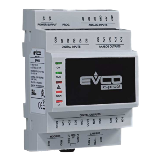
EVCO S.p.A. c-pro 3 micro CHIL | Application manual ver. 1.0 | Codice 144CP3CHE104 DIMENSIONS 4.1 Dimensions of controller and user interface Below we will show the dimensions, assembly and electric connections of the c-pro 3 micro CHIL. 4.1.1 Dimensionscontrol modulec-pro 3microCHILand c-pro 3 EXP micro+ 4 DIN modules, installation DIN rail mounting;... - Page 11 EVCO S.p.A. c-pro 3 micro CHIL | Application manual ver. 1.0 | Codice 144CP3CHE104 4.1.3 Dimensions module EVDRIVE03 4 DIN modules, installation DIN rail mounting; the dimensions arein mm(in). page 11 of 120...
-
Page 12: User Interface
EVCO S.p.A. c-pro 3 micro CHIL | Application manual ver. 1.0 | Codice 144CP3CHE104 USER INTERFACE For the application, two types of interface are provided: • Built-in LED-display interface • Remote LCD-display interface Vgraph. Both interfaces feature 6 keys for navigation/page editing, and differ in their display mode of certain associated statuses, i.e. via icons. -
Page 13: List Of
EVCO S.p.A. c-pro 3 micro CHIL | Application manual ver. 1.0 | Codice 144CP3CHE104 LIST OF PAGES This chapter describes the main pages and menus featured in the application. As already described earlier, the general menu is subdivided into four submenu levels: user, maintenance operator, installation operator, and configuration. -
Page 14: Password
EVCO S.p.A. c-pro 3 micro CHIL | Application manual ver. 1.0 | Codice 144CP3CHE104 Password Each menu is assigned a level, which affects the accessibility of the various menus. Each level is assigned a password, which enables access to the various functions featured in that menu; once the correct password has been entered, protected functions become accessible. -
Page 15: Unit On Main Page
EVCO S.p.A. c-pro 3 micro CHIL | Application manual ver. 1.0 | Codice 144CP3CHE104 Unit ON main page When the unit is turned on, the following main screen will be displayed: At the bottom of the page, icons will be displayed that indicate various statuses of circuit operation. -
Page 16: Menu Stat (Only For Display Led)
EVCO S.p.A. c-pro 3 micro CHIL | Application manual ver. 1.0 | Codice 144CP3CHE104 Menu StAt (Only for display LED) If the StAt voice is chosen from the general menu, several main statuses of the system are displayed (can be navigatedwith the... -
Page 17: Meaning Of Led (Only For Display Led)
Heaters: If on, it means that the strength of the antifreeze mechanism (heat sink or source) is active; if off, it means that no antifreeze mechanisms are active; if on and flashing slowly, it means that an antifreeze mechanism is in the alarm state. • EVCO. Icon linked to the functioning of parameter PH52. page 17 of 120... -
Page 18: General Menu
EVCO S.p.A. c-pro 3 micro CHIL | Application manual ver. 1.0 | Codice 144CP3CHE104 General Menu The general menu has no level and represents the access point for all the other system menus. Display LCD Display LED USER USEr MAINTENANCE... -
Page 19: Installer Menu
EVCO S.p.A. c-pro 3 micro CHIL | Application manual ver. 1.0 | Codice 144CP3CHE104 Installer Menu The installation menu is a Level 3 menu, i.e. it requires entering of the installation level (or higher) password, in order to be able to display/modify the parameters contained in this branch. -
Page 20: Constructor Menu
EVCO S.p.A. c-pro 3 micro CHIL | Application manual ver. 1.0 | Codice 144CP3CHE104 Constructor Menu The Configuration menu is a Level 4 menu, i.e. it requires entering of the Configuration level password, in order to be able to display/modify the parameters contained in this branch. Furthermore, this level is only accessible with the machine in OFF mode. -
Page 21: Parameters List
EVCO S.p.A. c-pro 3 micro CHIL | Application manual ver. 1.0 | Codice 144CP3CHE104 PARAMETERS LIST The parameters managed by the application are listed below. Each parameter is accompanied by a brief description, the range of its admissible values, units of measure, the assigned default value and the menu containing the parameter. Menus are structured on the... -
Page 22: List Of Configuration Parameters
EVCO S.p.A. c-pro 3 micro CHIL | Application manual ver. 1.0 | Codice 144CP3CHE104 List of Configuration Parameters Code Parameter Description Default Min. Max. M.U. Menu Notes RTC MEN - This menu is accessible ifPG03=1 PT01 Working day 1 enable zone 1... - Page 23 EVCO S.p.A. c-pro 3 micro CHIL | Application manual ver. 1.0 | Codice 144CP3CHE104 day1 2= working day2 0= none working day 1= working PT25 Friday schedule day1 2= working day2 0= none working day 1= working PT26 Saturday schedule...
- Page 24 EVCO S.p.A. c-pro 3 micro CHIL | Application manual ver. 1.0 | Codice 144CP3CHE104 limit is exceeded, the connected alarm is triggered. It shows the number of operating PM31 9999 Hrs. x10 MA-F hours of the first pump. It shows the number of operating Hrs.
- Page 25 EVCO S.p.A. c-pro 3 micro CHIL | Application manual ver. 1.0 | Codice 144CP3CHE104 operation of the source pump # 2. Water-Water 0: Auto – normal operation unit 1: Manu – manual operation Only for During manual operation, it forces the...
- Page 26 EVCO S.p.A. c-pro 3 micro CHIL | Application manual ver. 1.0 | Codice 144CP3CHE104 sensor Calibration of leaving temperature PM74 -10.0 10.0 °C MA-C sensor circuit 1 Calibration of leaving temperature PM75 -10.0 10.0 °C MA-C sensor circuit 2 Calibration of source leaving PM76 -10.0...
- Page 27 EVCO S.p.A. c-pro 3 micro CHIL | Application manual ver. 1.0 | Codice 144CP3CHE104 compressor. Min. time which must elapse between PC07 start-ups of two different Sec. IS-C compressors. Min. time which must elapse between PC08 shutdowns of two different Sec.
- Page 28 EVCO S.p.A. c-pro 3 micro CHIL | Application manual ver. 1.0 | Codice 144CP3CHE104 Pressure set point for high- PC46 27.0 45.0 IS-R temperature pressure-switch control Pressure differential for high- PC47 IS-R temperature pressure-switch control External high temperature threshold PC48 12.0...
- Page 29 EVCO S.p.A. c-pro 3 micro CHIL | Application manual ver. 1.0 | Codice 144CP3CHE104 control only if at least one compressor is ON. It sets whether or not fans must PF03 No (0) No (0) Yes (1) IS-F switch OFF during defrosting cycles.
- Page 30 EVCO S.p.A. c-pro 3 micro CHIL | Application manual ver. 1.0 | Codice 144CP3CHE104 2: Always With PF01=1 PF38 Preventilation speed 50.0 100.0 IS-F (Modulating Control) PF39 Preventilation time IS-F PF41 Value x1 of fan linearization table 25.0 PF42 IS-F...
- Page 31 EVCO S.p.A. c-pro 3 micro CHIL | Application manual ver. 1.0 | Codice 144CP3CHE104 Enabling of anti-frost heating Pr01 Yes (1) No (0) Yes (1) IS-AF elements Pr02 Anti-frost heating element set point Pr05 10.0 °C IS-AF Pr03 Anti-frost heating element differential 10.0...
- Page 32 EVCO S.p.A. c-pro 3 micro CHIL | Application manual ver. 1.0 | Codice 144CP3CHE104 during winter operation (heat pump) Triggering delay for temperature PA07 Sec. IS-S alarm Consequent time for a temperature alarm: PA08 Sec. IS-S 0 = Notification only...
- Page 33 EVCO S.p.A. c-pro 3 micro CHIL | Application manual ver. 1.0 | Codice 144CP3CHE104 with the compressor thermal alarm It sets the type of reset for the compressor thermal alarm PA42 A (0) M (1) IS-S 0: A - Automatic 1: M –...
- Page 34 EVCO S.p.A. c-pro 3 micro CHIL | Application manual ver. 1.0 | Codice 144CP3CHE104 Setpoint for the high temperature PA89 90.0 70.0 140.0 °C IS-S discharge gas alarm of circuit 2 Differential for the high temperature PA90 20.0 10.0 30.0 °C...
- Page 35 It sets the pressure measurement unit: PH33 0 (Bar) IS-V 0: Bar 1: psi PH52 It enable the EVCO icon IS-V It sets the meaning of the Summer and Winter icons. 0: Summer = Cooling (chiller mode) Winter = Heating (heat pump PH53 IS-V...
- Page 36 EVCO S.p.A. c-pro 3 micro CHIL | Application manual ver. 1.0 | Codice 144CP3CHE104 1: Yes (1 fan) unitdetermine s whether there are1/2 heat source exchangers Determines It enables single/twin whether there exchangerusers: PG12 Yes (1) No (0) Yes (1)
- Page 37 EVCO S.p.A. c-pro 3 micro CHIL | Application manual ver. 1.0 | Codice 144CP3CHE104 HC01 They set which analog resources to HC02 connect to analog outputs CO-HW HC03 1, 2, 3, 4 of the controller HC04 HC07 They set which analog resources to...
- Page 38 EVCO S.p.A. c-pro 3 micro CHIL | Application manual ver. 1.0 | Codice 144CP3CHE104 PV13 Setpoint HiSH (2) 15.0 10.0 40.0 CO-V PV14 Setpoint LOP (2) -40.0 -40.0 40.0 CO-V PV15 Setpoint MOP 2) 40.0 -40.0 40.0 CO-V PV16 PID –proportional band (2) 100.0...
- Page 39 EVCO S.p.A. c-pro 3 micro CHIL | Application manual ver. 1.0 | Codice 144CP3CHE104 7= PT1000 8= NTC K2 9= NTC K3 PV31 Ts offset -10.0 10.0 CO-V PV32 Te offset -10.0 10.0 CO-V PV34 Relay logic N.O. (0) N.O. (0) N.C.
- Page 40 EVCO S.p.A. c-pro 3 micro CHIL | Application manual ver. 1.0 | Codice 144CP3CHE104 6= solenoid valve 7= solenoid valve + alarms 8= resyncro Probe type 3: PV67 0= NTC CO-V 1= PT1000 Probe type 4: 0= 4..20mA (0.5 – 8) 1= 4..20mA (0 –...
-
Page 41: Ai Configuration (Ha01-Ha18 Parameters)
EVCO S.p.A. c-pro 3 micro CHIL | Application manual ver. 1.0 | Codice 144CP3CHE104 AI Configuration (HA01-HA18 parameters) Below is a table of values for configuring the positions of the analog inputs of the controller and of the expansion. The analog inputs can be configured as digital inputs as well. -
Page 42: Di Configuration(Hb01-Hb18 Parameters)
EVCO S.p.A. c-pro 3 micro CHIL | Application manual ver. 1.0 | Codice 144CP3CHE104 DI Configuration(HB01-HB18 parameters) Below is a table of values for configuring the positions of the digital inputs of the controller and of the expansion. HB01-HB18 Parameters... -
Page 43: Do Configuration (Hd01-Hd18 Parameters)
EVCO S.p.A. c-pro 3 micro CHIL | Application manual ver. 1.0 | Codice 144CP3CHE104 DO Configuration (HD01-HD18 parameters) Below is a table of values for configuring the positions of the digital outputs of the controller and of the expansion. Parameters... -
Page 44: Regulations
EVCO S.p.A. c-pro 3 micro CHIL | Application manual ver. 1.0 | Codice 144CP3CHE104 REGULATIONS Machine Status Several procedures exist for switching the unit ON and OFF: 1) Using the dedicated ON/OFF key (this function is enabled via parameter PH05). -
Page 45: Unit Type
EVCO S.p.A. c-pro 3 micro CHIL | Application manual ver. 1.0 | Codice 144CP3CHE104 Unit Type With the machine in OFF status, using the PGUT parameter from the CONSTRUCTOR/CONFIGURATION menu, it is possible to select the unit type to be used. Control and other parameters corresponding to the various functions must be manually modified according to user requirements. -
Page 46: Water-To-Water Chiller
EVCO S.p.A. c-pro 3 micro CHIL | Application manual ver. 1.0 | Codice 144CP3CHE104 8.2.2 Water-To-Water Chiller PGUT=2 (1 Circuit) PGUT=10 (2 Circuit) Controller Analog Inputs A/I 1 Heat sink exchanger input temperature Heat sink exchanger input temperature A/I 2... -
Page 47: Water-To-Water Chiller+Heat Pump With Evdrive03
EVCO S.p.A. c-pro 3 micro CHIL | Application manual ver. 1.0 | Codice 144CP3CHE104 8.2.3 Water-To-Water Chiller+Heat Pump with EVDRIVE03 PGUT=3 (1 Circuit) PGUT=11 (2 Circuit) Controller Analog Inputs A/I 1 Heat sink exchanger input temperature Heat sink exchanger input temperature... -
Page 48: Water-To-Water Chiller+Heat Pump
EVCO S.p.A. c-pro 3 micro CHIL | Application manual ver. 1.0 | Codice 144CP3CHE104 D/O 2 Not present Compressor 5 D/O 3 Not present Reversing valve C2 Digital OutputsEVDRIVE03 circuit 1 D/O VCM 1 Solenoid valve C1 Solenoid valve C1... -
Page 49: Air-To-Water Chiller With Evdrive03
EVCO S.p.A. c-pro 3 micro CHIL | Application manual ver. 1.0 | Codice 144CP3CHE104 D/O 3 Not present Reversing valve C2 D/O 4 Not present Solenoid valve C2 8.2.5 Air-To-Water Chiller with EVDRIVE03 PGUT=5 (1 Circuit) PGUT=13 (2 Circuit) Controller Analog Inputs... -
Page 50: Air-To-Water Chiller
EVCO S.p.A. c-pro 3 micro CHIL | Application manual ver. 1.0 | Codice 144CP3CHE104 8.2.6 Air-To-Water Chiller PGUT=6 (1 Circuit) PGUT=14 (2 Circuit) Controller Analog Inputs A/I 1 Heat sink exchanger input temperature Heat sink exchanger input temperature A/I 2... -
Page 51: Air-To-Water Chiller+Heat Pump With Evdrive03
EVCO S.p.A. c-pro 3 micro CHIL | Application manual ver. 1.0 | Codice 144CP3CHE104 8.2.7 Air-To-Water Chiller+Heat Pump with EVDRIVE03 PGUT=7 (1 Circuit) PGUT=15 (2 Circuit) Controller Analog Inputs A/I 1 Heat sink exchanger input temperature Heat sink exchanger input temperature... -
Page 52: Air-To-Water Chiller+Heat Pump
EVCO S.p.A. c-pro 3 micro CHIL | Application manual ver. 1.0 | Codice 144CP3CHE104 D/O 4 Not present Reversing valve C2 Digital OutputsEVDRIVE03 circuit 1 D/O VCM 1 Solenoid valve C1 Solenoid valve C1 Digital Outputs EVDRIVE03 circuit 2 D/O VCM 2... -
Page 53: Configuration Of Circuits
EVCO S.p.A. c-pro 3 micro CHIL | Application manual ver. 1.0 | Codice 144CP3CHE104 CAUTION! When the machine type is changed, it is necessary to switch OFF and then back ON the plant, to enable the unit to reconfigure itself correctly; to allow the card to assign all affected parameters, it is advisable to wait for a few seconds (3 seconds are more than ample time), before interrupting the unit’s power supply. -
Page 54: Operating Mode Control
EVCO S.p.A. c-pro 3 micro CHIL | Application manual ver. 1.0 | Codice 144CP3CHE104 Operating Mode Control The operating mode can take on the following values: “MOdE” parameter Operating mode Description 0=CooL Chiller Summer operation 1=Heat Heat pump (*) Winter operation (*) Heat pump operation is only possible if the machine has been configured as chiller + heat pump (parameter PG00=2,4). -
Page 55: Setting The Rtc
EVCO S.p.A. c-pro 3 micro CHIL | Application manual ver. 1.0 | Codice 144CP3CHE104 Setting the RTC When the power supply is disconnected from the controller for a few days, the RTC (Real Time Clock) system clock loses its time. When the controller power is up again, it requires to reset the RTC alarm (enabled by PA30=1) and setting the correct date and time. -
Page 56: Compressor Control
EVCO S.p.A. c-pro 3 micro CHIL | Application manual ver. 1.0 | Codice 144CP3CHE104 Compressor Control The control of water temperature (air-to-water or water-to-water machines) is carried out via the control of mechanical components, i.e. compressors and/or fans. Two types of control are provided: lateral-band control on entering chilled water temperature and zero energy band control on leaving chilled water temperature. -
Page 57: Zero Energy Band (Zeb) Control
EVCO S.p.A. c-pro 3 micro CHIL | Application manual ver. 1.0 | Codice 144CP3CHE104 PC12 = Proportional band PC23 = Heat pump set point lower limit PC24 = Heat pump set point upper limit 8.6.2 Zero energy band (ZEB) control This control type requires the definition of a zero energy band (ZEB) around the set point. -
Page 58: Auto Adaptive Control
EVCO S.p.A. c-pro 3 micro CHIL | Application manual ver. 1.0 | Codice 144CP3CHE104 8.6.3 Auto adaptive control If the CHW leaving temperature still remains outside the zero energy band, even after the extra-time interval set in parameter PC17 has elapsed, the switching ON or OFF of a further power step will be requested. -
Page 59: Pump-Down Switch-Off Procedure
EVCO S.p.A. c-pro 3 micro CHIL | Application manual ver. 1.0 | Codice 144CP3CHE104 last compressor to be switched OFF is stored in memory, then the next compressor in the sequence is switched ON, so as to avoid always using the same compressor, thus exploiting in a better manner all configured elements. -
Page 60: Protection Timings
EVCO S.p.A. c-pro 3 micro CHIL | Application manual ver. 1.0 | Codice 144CP3CHE104 Last compressor request Evap. P PC43 Pump-down pressure differential Solenoid valve Compressor PC42 Pump-down disable delay Anyway, there is always the Compressor switch-OFF delay in pump-down, should the switch-OFF pressure threshold not be reached, or should evaporation sensors be faulty. -
Page 61: Thermal Protection Inputs
EVCO S.p.A. c-pro 3 micro CHIL | Application manual ver. 1.0 | Codice 144CP3CHE104 Neutral-zone timings These parameters are used to time the request for switching ON/OFF the various compressors. PC17 = Extra time for ON/OFF switching request 8.7.6 Thermal protection inputs The program provides for the management of a compressor thermal safety switch input for each compressor. - Page 62 EVCO S.p.A. c-pro 3 micro CHIL | Application manual ver. 1.0 | Codice 144CP3CHE104 Speed SPF - Y 100% High speed Low speed SP - X SP + diff Pressure Mode = Operating mode (0 = Summer) PF11 = Summer condensation control set point (SP)
- Page 63 EVCO S.p.A. c-pro 3 micro CHIL | Application manual ver. 1.0 | Codice 144CP3CHE104 Speed SPF + Y Max. speed High speed Low speed SP - diff SP + X Pressure Mode = Operating mode (1 = Winter) PF21 = Winter condensation control set point (SP)
-
Page 64: Single Stage Fan Control
EVCO S.p.A. c-pro 3 micro CHIL | Application manual ver. 1.0 | Codice 144CP3CHE104 8.8.2 Single stage fan control Manage a single stage control of condenser fans by a digital output for every fan. The condenser fan is switched on when the condenser pressure exceeds the condenser setpoint + condenser pressure differential. The condenser fan is switched off when the condenser pressure falls below the condenser setpoint, see also next picture. -
Page 65: Fan Management
EVCO S.p.A. c-pro 3 micro CHIL | Application manual ver. 1.0 | Codice 144CP3CHE104 Fan Management The program is capable of managing up to 2 fans, i.e. one for each circuit. It is possible to associate to each fan a safety digital input and a digital output for ON/OFF switching. -
Page 66: Circulating Pump Management
EVCO S.p.A. c-pro 3 micro CHIL | Application manual ver. 1.0 | Codice 144CP3CHE104 8.10 Circulating Pump Management On AIR-TO-WATER or WATER-TO-WATER machines, 1 or 2 water-circulating pumps can be controlled, which are defined by the parameter PG09. The Pump operation PP01 parameter defines how the pump will operate:... -
Page 67: Pump Status
EVCO S.p.A. c-pro 3 micro CHIL | Application manual ver. 1.0 | Codice 144CP3CHE104 8.10.1 Pump Status To each pump, an operating status is associated, which is visible from the associated LED or in the status template from the main menu. -
Page 68: Circulating Source Pump Management
EVCO S.p.A. c-pro 3 micro CHIL | Application manual ver. 1.0 | Codice 144CP3CHE104 8.11 Circulating Source Pump Management On WATER-TO-WATER machines, 1 or 2 source water-circulating pumps can be controlled, which are defined by the parameter PG10. The Pump operation PP21 parameter defines how the pump will operate. -
Page 69: Defrosting Cycle Compensation
EVCO S.p.A. c-pro 3 micro CHIL | Application manual ver. 1.0 | Codice 144CP3CHE104 8.12.1 Defrosting cycle compensation With the decreasing of the outdoor air temperature, the water vapor content in the air (which causes the formation of frost on the evaporation battery, thus creating a need for defrosting) decreases, and it may therefore be advantageous to increase the defrosting- activation delay in relation to the decrease in the outdoor air temperature, to improve the overall efficiency of the system. -
Page 70: Free-Cooling Management
EVCO S.p.A. c-pro 3 micro CHIL | Application manual ver. 1.0 | Codice 144CP3CHE104 8.15 Free-Cooling Management To obtain significant energy savings in the management of the system, the chiller has the possibility of using external air, when the air has favourable thermal characteristics, to take advantage of its energy content and to obtain “free cooling”. - Page 71 EVCO S.p.A. c-pro 3 micro CHIL | Application manual ver. 1.0 | Codice 144CP3CHE104 Fan Speed Set Point FC PS02 PS04 PS03 PS08 Set Point BL T. Regulation When the temperature reaches the FC Set Point and remains below for more than PS10 seconds, it deactivates free-cooling; the step shown in the diagram, hysteresis PS08(default 0.5°C), re-enables free-cooling andthe ramp (if ON status is maintained for more than...
-
Page 72: Free-Cooling Control Valve
EVCO S.p.A. c-pro 3 micro CHIL | Application manual ver. 1.0 | Codice 144CP3CHE104 8.15.3 Free-Cooling control valve In a case where the valve is of the ON/OFF type, the activation control will follow the consensus step on Set Point FC, with PS08hysteris, described earlier. -
Page 73: Temperature Alarm Control
EVCO S.p.A. c-pro 3 micro CHIL | Application manual ver. 1.0 | Codice 144CP3CHE104 8.16 Temperature Alarm Control 8.16.1 Low and high temperature alarm management According to operating mode, a check is carried out on the exchanger inlet temperature, triggering an alarm where appropriate. -
Page 74: Management Of Low-Pressure Transducer Alarm (Heat Pump Mode)
EVCO S.p.A. c-pro 3 micro CHIL | Application manual ver. 1.0 | Codice 144CP3CHE104 • PA13 = Low-pressure alarm by-pass time • PA14 = Maximum number of auto-reset low-pressure alarms If, with the machine switched ON and in the presence of a request for chill from the controller, low pressure is detected, compressor start-up is inhibited and a Start-up low-pressure alarm AL21 (and AL22 for Circuit # 2) is displayed. -
Page 75: Time Schedule
EVCO S.p.A. c-pro 3 micro CHIL | Application manual ver. 1.0 | Codice 144CP3CHE104 8.18 Time schedule The real time clock allows the operator to define a weekly schedule for the unit. Two different daily schedules can be defined. Each daily schedule can have 2 zones with separate heating and cooling offset values. -
Page 76: Miscellaneous Management
EVCO S.p.A. c-pro 3 micro CHIL | Application manual ver. 1.0 | Codice 144CP3CHE104 8.19 Miscellaneous Management 8.19.1 Set point variation by schedule timer Via parameter PH28 it is possible to adjust the setpoint by the schedule timer (set relative parameters of scheduler). Actual control setpoint depends by the working day and relative offset. -
Page 77: Forced Shutdown
EVCO S.p.A. c-pro 3 micro CHIL | Application manual ver. 1.0 | Codice 144CP3CHE104 8.19.3 Forced shutdown This function enables the forced shutdown of all compressors, when CHW leaving temperature falls below the Summer forced-shutdown set point (in the case of chiller operation), or exceeds the Winter forced-shutdown set point (in the case of heat-pump operation). -
Page 78: Low-Pressure Partialization At Low Temperatures (Heat Pump)
EVCO S.p.A. c-pro 3 micro CHIL | Application manual ver. 1.0 | Codice 144CP3CHE104 8.19.5 Low-pressure partialization at low temperatures (heat pump) This control makes it possible to partialize the refrigerating circuit power when outdoor air temperature and refrigerated water temperature conditions lead to the triggering of minimum-pressure alarms. -
Page 79: Operating Limit Management (Heat Pump)
EVCO S.p.A. c-pro 3 micro CHIL | Application manual ver. 1.0 | Codice 144CP3CHE104 8.19.6 Operating limit management (heat pump) When the external air temperature falls to particularly low levels, it may no longer be convenient or sufficient to heat using the heat pump. -
Page 80: Management Of Evdrive03 Integrated Into The System
EVCO S.p.A. c-pro 3 micro CHIL | Application manual ver. 1.0 | Codice 144CP3CHE104 8.20 Management of EVDRIVE03 integrated into the system The management of the electronic valve must be optimised and not limited to a classical overheating control. There are several conditions and regulations that must consider other system variables as a whole, as well as the overheating variables (evaporation temperature and pressure) in a way to limit the problems due to the delays introduced by the temperature probe in the same and its positioning. -
Page 81: Manual Operation
EVCO S.p.A. c-pro 3 micro CHIL | Application manual ver. 1.0 | Codice 144CP3CHE104 8.21 Manual operation The program allows the setting of manual operation for compressors, fans and pumps. In this condition, devices are not involved in rotations, nor in thermo control calculations, although they do remain sensitive to any alarms. -
Page 82: Resetting Of Default Parameters
EVCO S.p.A. c-pro 3 micro CHIL | Application manual ver. 1.0 | Codice 144CP3CHE104 8.22 Resetting of default parameters Using the “Parameter resetting” procedure, all system parameters can be reset to their original default values. After entering the InSt- >MAP menu – which is only accessible while the machine is switched OFF – set parameter PH15=1 and wait for the “0” value to reappear on the display;... -
Page 83: Wiring Diagram
EVCO S.p.A. c-pro 3 micro CHIL | Application manual ver. 1.0 | Codice 144CP3CHE104 WIRING DIAGRAM 9.1 Connection layout c-pro 3 micro CHIL The following table shows the connection layout of c-pro 3 micro CHIL. c-pro 3 micro CHIL Digital outputs 1… 7... - Page 84 EVCO S.p.A. c-pro 3 micro CHIL | Application manual ver. 1.0 | Codice 144CP3CHE104 Terminal 0 of the transceiver Analog inputs 7… 9, digital inputs 6… 9 and analog outputs 4… 6. TERMINAL MEANING Commonanalog inputs and analog outputs Analog input 7...
-
Page 85: Connection Layout C-Pro 3 Exp Micro
EVCO S.p.A. c-pro 3 micro CHIL | Application manual ver. 1.0 | Codice 144CP3CHE104 9.2 Connection layout c-pro 3 EXP micro+ The following table shows the connection layout of c-pro 3 EXP micro+ c-pro 3 EXP micro+ Digital outputs 1… 7... - Page 86 EVCO S.p.A. c-pro 3 micro CHIL | Application manual ver. 1.0 | Codice 144CP3CHE104 Analog input 9 Analog output 4 Analog output 5 Analog output 6 Digital input 6 Digital input 7 Digital input 8 Digital input 9 Common digital inputs...
-
Page 87: Connection Layout Evdrive03
EVCO S.p.A. c-pro 3 micro CHIL | Application manual ver. 1.0 | Codice 144CP3CHE104 9.3 Connection layout EVDRIVE03 The following table shows the connection layout of EVDRIVE03 EVDRIVE03 Digital output TERMINAL MEANING Common digital output Normally open contact digital output... - Page 88 EVCO S.p.A. c-pro 3 micro CHIL | Application manual ver. 1.0 | Codice 144CP3CHE104 Bipolar stepper motor output TERMINAL MEANING V BATT Backup power supply input SHIELD Common bipolar stepper SO 1A Bipolar stepper motor coil 1 SO 1B Bipolar stepper motor coil 1...
-
Page 89: Connection Layout Vgraph
EVCO S.p.A. c-pro 3 micro CHIL | Application manual ver. 1.0 | Codice 144CP3CHE104 9.4 Connection layout Vgraph The following table shows the connection layout of Vgraph Vgraph Connector 1: CAN port MEANING Ground Signal - Signal + Connector 2: power supply... -
Page 90: C-Pro 3 Micro Chil
EVCO S.p.A. c-pro 3 micro CHIL | Application manual ver. 1.0 | Codice 144CP3CHE104 9.5 c-pro 3 micro CHIL The power supply of the devices must be galvanically isolated among them. page 90 of 120... -
Page 91: 10 9.5.1 Table Of Connection C-Pro 3 Micro Chil
EVCO S.p.A. c-pro 3 micro CHIL | Application manual ver. 1.0 | Codice 144CP3CHE104 9.5.1 Table of connection c-pro 3 micro CHIL PGUT=11 (2 Circuit) Controller Analog Inputs A/I 1 Heat sink exchanger input temperature A/I 2 Heat sink exchanger output temperature... -
Page 92: Diagnostics
EVCO S.p.A. c-pro 3 micro CHIL | Application manual ver. 1.0 | Codice 144CP3CHE104 DIAGNOSTICS The application is capable of managing a whole series of alarms, relating to compressors, fans, circuits and plant functions. Depending on the various alarm types, it is possible to configure their resetting (whether manual or automatic), a possible notification delay and any actions to be taken in that specific case. -
Page 93: Alarm Table
EVCO S.p.A. c-pro 3 micro CHIL | Application manual ver. 1.0 | Codice 144CP3CHE104 10.4 Alarm Table All alarms managed by the application are listed below. The listing order is the same as the one in which alarms are listed when active. - Page 94 EVCO S.p.A. c-pro 3 micro CHIL | Application manual ver. 1.0 | Codice 144CP3CHE104 AC02 Operating hours compressor #2 Auto Display only AC03 Operating hours compressor #3 Auto Display only AC04 Operating hours compressor #4 Auto Display only AC05 Operating hours compressor #5...
- Page 95 EVCO S.p.A. c-pro 3 micro CHIL | Application manual ver. 1.0 | Codice 144CP3CHE104 Note: (*¹) If this is the only pump, it switches OFF all compressors and fans; otherwise, it switches ON the other pump. S/A = Notification - only or auto-reset alarm (settable via parameter).
-
Page 96: Alarms History
EVCO S.p.A. c-pro 3 micro CHIL | Application manual ver. 1.0 | Codice 144CP3CHE104 10.5 Alarms History The controller memorizes in a suitable (non volatile) memory zone organized like the FIFO queue, the ALARM HISTORY, or rather it could be a list of the last alarms verified. -
Page 97: List Of Modbus® Variables
EVCO S.p.A. c-pro 3 micro CHIL | Application manual ver. 1.0 | Codice 144CP3CHE104 LIST OF Modbus® VARIABLES ® The application can be controlled via a supervisor, using the Modbus protocol. Communication takes place via an RS485 serial interface, which is already incorporated into the controller. - Page 98 EVCO S.p.A. c-pro 3 micro CHIL | Application manual ver. 1.0 | Codice 144CP3CHE104 Probe_TGasDischar 0x020F 3276.7 ge_C2 3276.8 0x0210 Probe_TSuction_C2 3276.7 3276.8 0x0211 Probe_PCond_C2 3276.7 3276.8 0x0212 Probe_PEvap_C2 3276.7 3276.8 0x0213 Probe_PUnique_C2 3276.7 3276.8 0x0280 vAO_Fan_C1 0.00 0.00 100.00...
- Page 99 EVCO S.p.A. c-pro 3 micro CHIL | Application manual ver. 1.0 | Codice 144CP3CHE104 0x031A BMS_AL61 0x031B BMS_AL62 0x031C BMS_AL81 0x031D BMS_AL82 0x031E BMS_AL83 0x031F BMS_AL84 0x0320 BMS_AP21 0x0321 BMS_AP22 0x0322 BMS_AP23 0x0323 BMS_AP24 0x0324 BMS_ERTC 0x0400 1025 OnOffBySuperv ON/OFF machine by supervisor...
- Page 100 EVCO S.p.A. c-pro 3 micro CHIL | Application manual ver. 1.0 | Codice 144CP3CHE104 0x0514 1301 UI_FanStatus[0] UI_defrost_C1orC2[ 0x0515 1302 Defrost status (circuit) 0x0516 1303 vCntOnDefrost_C2 65535 0x0517 1304 vCntWatDefrost_C2 65535 StatusCompressors[ 0x0518 1305 Status compressor StatusCompressors[ 0x0519 1306 Status compressor...
- Page 101 EVCO S.p.A. c-pro 3 micro CHIL | Application manual ver. 1.0 | Codice 144CP3CHE104 PT15_OffsetHeating 0x0614 1557 -36.0 36.0 PT15 - Offset heating day 2 zone 1 Day2TZ_1 PT16_enabWorking 0x0615 1558 PT16 - Enable zone 2 of working day 2...
- Page 102 EVCO S.p.A. c-pro 3 micro CHIL | Application manual ver. 1.0 | Codice 144CP3CHE104 PM03_OperatingHo 0x062F 1584 ursCmp3 ( High ) PM04_OperatingHo 0x0630 1585 9999.0 PM04 - Operating Hours Cmp 4 ursCmp4 ( Low ) PM04_OperatingHo 0x0631 1586 ursCmp4 ( High )
- Page 103 EVCO S.p.A. c-pro 3 micro CHIL | Application manual ver. 1.0 | Codice 144CP3CHE104 ance ( Low ) 1/20 2000 2068 3.14.0 PM90_Last_mainten 0x0649 1610 ance ( High ) PM11a16_EnabMan 0x064A 1611 PM11 - Enable compressors manual operation ual_Comp[0] PM11a16_EnabMan...
- Page 104 EVCO S.p.A. c-pro 3 micro CHIL | Application manual ver. 1.0 | Codice 144CP3CHE104 Fan_C1 PM64_ForzaturaInv 0x0663 1636 PM64 - Manual operation condensing fan Circuit # 2 Fan_C2 PM65_EnManuFan_ 0x0664 1637 PM66_ForceFanAO_ 0x0665 1638 0.00 0.00 100.00 PM67_ForseFanDO_ 0x0666 1639...
- Page 105 EVCO S.p.A. c-pro 3 micro CHIL | Application manual ver. 1.0 | Codice 144CP3CHE104 PC07_Cmp_TonOth 0x067E 1663 PC07 - Min time between 2 startup of different comp PC08_Cmp_ToffOth PC08 - Min time between 2 shutdown of different 0x067F 1664 comp...
- Page 106 EVCO S.p.A. c-pro 3 micro CHIL | Application manual ver. 1.0 | Codice 144CP3CHE104 PC49 - Min. time for maintaining pressure-switch 0x0699 1690 PC49_MinTimeHPTC partialization PC50_EnabPressCo PC50 Enable low-temperature pressure-switch 0x069A 1691 ntrolLT control (heat pump) PC51_SetControlPre PC51 Pressure setpoint...
- Page 107 EVCO S.p.A. c-pro 3 micro CHIL | Application manual ver. 1.0 | Codice 144CP3CHE104 PF03_StopFan_Defr 0x06B3 1716 PF03- Stop fan during defrost 0x06B4 1717 PF07_Fan_TonOther PF07 - Fan Min Time between 2 starts 0x06B5 1718 PF08_Fan_ToffOther PF08 - Min Time between 2 fan shutdown...
- Page 108 EVCO S.p.A. c-pro 3 micro CHIL | Application manual ver. 1.0 | Codice 144CP3CHE104 PF45_LinInverterFa 25.0 0x06CF 1744 0.00 100.00 PF46_LinInverterFa 50.0 0x06D0 1745 0.00 100.00 PF47_LinInverterFa 75.0 0x06D1 1746 0.00 100.00 Pd01_SetStartDefro 0x06D2 1747 652.5 Pd01 - Setpoint start defrost...
- Page 109 EVCO S.p.A. c-pro 3 micro CHIL | Application manual ver. 1.0 | Codice 144CP3CHE104 Pr06_DiffAlarmAntif 0x06EB 1772 18.0 Pr06 - Differential alarm antifreeze reeze Pr11_EnableAntiFre 0x06EC 1773 Pr11 - Enable antifreeze heater ezeHeater_Src Pr12_SetpointHeate 0x06ED 1774 -30.0 50.0 Pr12 - Setpoint heater...
- Page 110 EVCO S.p.A. c-pro 3 micro CHIL | Application manual ver. 1.0 | Codice 144CP3CHE104 meForTempAlarm PA09_DifferentialAla 0x0707 1800 18.0 PA09 - Differential alarm high/low temperature rmTemp PA10_DelayAfterUni 0x0708 1801 PA10 - Delay temperature alarm after unit on PA11_SetAlarmLow 0x0709 1802 143.5...
- Page 111 EVCO S.p.A. c-pro 3 micro CHIL | Application manual ver. 1.0 | Codice 144CP3CHE104 PA60_En_Alarm_Ho 0x0722 1827 PA60 - Enable alarm operating hours pumps urPump PA61_En_Alarm_Ho 0x0723 1828 ur_SourcePump PA62_ThermalPump 0x0724 1829 _ResetType PA63_ThermalSorgP 0x0725 1830 ump_ResetType PA71_RestoreTypeH 0x0726 1831...
- Page 112 EVCO S.p.A. c-pro 3 micro CHIL | Application manual ver. 1.0 | Codice 144CP3CHE104 2=4800, 3=9600, 4=19200, 5=28800, 6=38400, 7=57600 PH13_Modbus_Parit 0x073D 1854 PH13 - Modbus parity 0=NONE, 1=ODD, 2=EVEN PH14_Modbus_Stop 0x073E 1855 PH14 - Modbus stop bit 0=1 stop bit, 1=2 stop bits...
- Page 113 EVCO S.p.A. c-pro 3 micro CHIL | Application manual ver. 1.0 | Codice 144CP3CHE104 PG13_FreeCool_Air 0=Uniquewith Condensing, 0x0756 1879 Circuit 1=Separated FAN AO, 2=Separated FAN DO PG14_enabSingleEx 0x0757 1880 c_Source 0x0758 1881 HA01 0x0759 1882 HA02 0x075A 1883 HA03 0x075B...
- Page 114 EVCO S.p.A. c-pro 3 micro CHIL | Application manual ver. 1.0 | Codice 144CP3CHE104 0x077D 1918 HC02 0x077E 1919 HC03 0x077F 1920 HC04 0x0780 1921 HC05 0x0781 1922 HC06 0x0782 1923 HC07 0x0783 1924 HC08 0x0784 1925 HC09 0x0785 1926...
- Page 115 EVCO S.p.A. c-pro 3 micro CHIL | Application manual ver. 1.0 | Codice 144CP3CHE104 PV06_PIDpropBand 0x07A2 1955 100.0 °K 1_VC1 PV07_PIDintegralTi 0x07A3 1956 me1_VC1 PV08_PIDderivTime 0x07A4 1957 1_VC1 PV09_StartUpDelay 0x07A5 1958 1_VC1 PV10_StartUpPositi 50.0 0x07A6 1959 0.00 100.00 on1_VC1 PV11_SHsetpoint2_...
- Page 116 EVCO S.p.A. c-pro 3 micro CHIL | Application manual ver. 1.0 | Codice 144CP3CHE104 PV32_TeTemperatur 0x07BC 1981 -10.0 10.0 °K eOffset_VC1 PV34_RelayLogic_V 0x07BD 1982 0x07BE 1983 PV35_DI1Logic_VC1 0x07BF 1984 PV36_DI2Logic_VC1 PV37_DIHVLogic_V 0x07C0 1985 PV41_SHsetpoint1_ 0x07C1 1986 25.0 °K PV42_LoSHsetpoint 0x07C2 1987 °K...
- Page 117 EVCO S.p.A. c-pro 3 micro CHIL | Application manual ver. 1.0 | Codice 144CP3CHE104 ode_VC2 PV64_ManualValveP 0x07D8 2009 0.00 0.00 100.00 ositionSetPoint_VC2 PV65_SHcontrolPar 0x07D9 2010 ametersSet_VC2 PV66_RelayFuncSel 0x07DA 2011 _VC2 PV67_AIV3probeTy 0x07DB 2012 0=NTC, 1=PT1000 pe_VC2 0=4..20mA(0.5-8), 1=4..20mA(0-30), 2=0_5V(0-7), PV68_AIV4probeTy...
- Page 118 EVCO S.p.A. c-pro 3 micro CHIL | Application manual ver. 1.0 | Codice 144CP3CHE104 PSd1_Password_Us 0x07EF 2032 -999 9999 PSd1 - User password PSd2_Password_Mai 0x07F0 2033 -999 9999 PSd2 - Maintain Password ntenance PSd3_Password_Ins 0x07F1 2034 -999 9999 PSd3 - Installer Password...
- Page 119 This document is exclusive property of EVCO. Reproduction and disclosure are prohibited without express authorisation from EVCO. EVCO is not liable for any features, technical data and possible errors stated in this document or deriving from use of the same.
- Page 120 EVCO S.p.A. c-pro 3 micro CHIL | Application manual ver. 1.0 | Codice 144CP3CHE104 EVCO S.p.A. Via Feltre 81, 32036 SedicoBelluno ITALIA Tel. 0437/8422 | Fax 0437/83648 info@evco.it | www.evco.it page 120 of 120...
- Page 121 c-pro 3 nano Programmable controllers (up to 25 I/O) Hardware Manual | ENGLISH Code 114CP3NE104 TheInnovationEvolution...
- Page 122 EVCO S.p.A. c-pro 3 nano | Hardware Manual ver. 1.0 | Code 114CP3NE104 IMPORTANT Read this document carefully before installation and before using the device and take all the prescribed precautions. Keep this document with the device for future consultation.
- Page 123 EVCO S.p.A. c-pro 3 nano | Hardware Manual ver. 1.0 | Code 114CP3NE104 Index INTRODUCTION ................5 Initial information..............5 Main features of the models available and purchasing codes ..6 DESCRIPTION ................7 MEASUREMENTS AND INSTALLATION ..........7 Measurements ................. 7 Installation ................
- Page 124 EVCO S.p.A. c-pro 3 nano | Hardware Manual ver. 1.0 | Code 114CP3NE104 page 4 of 26...
- Page 125 EVCO S.p.A. c-pro 3 nano | Hardware Manual ver. 1.0 | Code 114CP3NE104 INTRODUCTION Initial information c-pro 3 nano is a range of extremely compact programmable controllers with numerous inputs and outputs (up to 25) and with an enhanced memory capacity to meet the management needs of the HVAC/R sector and OEM companies in particular.
- Page 126 EVCO S.p.A. c-pro 3 nano | Hardware Manual ver. 1.0 | Code 114CP3NE104 Main features of the models available and purchasing codes The table below shows the main features of the models available and the purchasing codes. MAIN FEATURES MODELS AVAILABLE AND PURCHASING CODES...
- Page 127 EVCO S.p.A. c-pro 3 nano | Hardware Manual ver. 1.0 | Code 114CP3NE104 DESCRIPTION MEASUREMENTS AND INSTALLATION The picture below shows the appearance of the devices. Measurements The picture below shows the measurements of the devices. Measurements are expressed in mm (inches).
- Page 128 EVCO S.p.A. c-pro 3 nano | Hardware Manual ver. 1.0 | Code 114CP3NE104 The tables below describe the connectors. ELECTRICAL CONNECTION N.B. Connector 1 - Do not supply further devices with the same transformer. DESCRIPTION - Use cables of an adequate section for the current running analogue input 6 (for PTC, NTC or Pt 1000 probes;...
- Page 129 EVCO S.p.A. c-pro 3 nano | Hardware Manual ver. 1.0 | Code 114CP3NE104 Connection to the power supply dry contact digital input) The picture below shows the c-pro 3 nano plus connection to the power supply. digital input 5 (dry contact) analogue input 9 (for NTC probes, 0-5 V ratiometric transducers, 0- 10 V, 0-20 mA or 4-20 mA transducers;...
- Page 130 EVCO S.p.A. c-pro 3 nano | Hardware Manual ver. 1.0 | Code 114CP3NE104 Analogue output wiring diagram RS-485 MODBUS port wiring diagram The picture below shows the c-pro 3 nano plus analogue output connection. The picture below shows an example of c-pro 3 nano plus RS-485 MODBUS port connection.
- Page 131 - Disconnect the power supply before doing any type of maintenance. - Do not use the device as safety device. - For repairs and for further information, contact the EVCO sales network. 4.11 USB flash drive connection The picture below shows a USB flash drive connection to the c-pro 3 nano plus.
- Page 132 EVCO S.p.A. c-pro 3 nano | Hardware Manual ver. 1.0 | Code 114CP3NE104 FIRST-TIME USE DEVICE CONFIGURATION Proceed as follows. N.B. Install following the instructions given in the section MEASUREMENTS - The use of the DOWN key as an entity in the application software AND INSTALLATION.
- Page 133 EVCO S.p.A. c-pro 3 nano | Hardware Manual ver. 1.0 | Code 114CP3NE104 If option available, to set the language for viewing the application software Lower line Hour (00… 23) proceed as follows. Touch the SET key. Touch the UP or DOWN key to select the current viewing label, for example the label “EnG”...
- Page 134 EVCO S.p.A. c-pro 3 nano | Hardware Manual ver. 1.0 | Code 114CP3NE104 To download the device configuration using a USB flash drive proceed as To upload the device configuration using a USB flash drive proceed as follows. follows. Connect a USB flash drive to the device as shown in the section Connect a USB flash drive to the device as shown in the section USB flash drive connection.
- Page 135 EVCO S.p.A. c-pro 3 nano | Hardware Manual ver. 1.0 | Code 114CP3NE104 List of hardware parameters The table below shows the hardware parameters of the device. The hardware parameter values are overwritten by the parameter values of the application software.
- Page 136 EVCO S.p.A. c-pro 3 nano | Hardware Manual ver. 1.0 | Code 114CP3NE104 0-20 0-20 mA 0-20mA 4-20 4-20 mA 4-20mA AI 2 0-5 V ratiometric type of probe analogue input 2 Parameters AI 2 0-5V 0-10 0-10 V 0-10V...
- Page 137 EVCO S.p.A. c-pro 3 nano | Hardware Manual ver. 1.0 | Code 114CP3NE104 AI 7 Pt10 Pt 1000 type of probe analogue input 7 Parameters AI 7 PT1000 electric heater reading RESIST not available Parameters AI 8 Pt10 Pt 1000...
- Page 138 EVCO S.p.A. c-pro 3 nano | Hardware Manual ver. 1.0 | Code 114CP3NE104 0-20 0-20 mA Parameters 0-20mA AO 3 010V 4-20 4-20 mA type of signal analogue output 3 only available AO 3 0-10V 4-20mA for c-pro 3 nano...
- Page 139 EVCO S.p.A. c-pro 3 nano | Hardware Manual ver. 1.0 | Code 114CP3NE104 nEt > CAn Networks > CAN nLoG NetworkNode CAN network device node [1]... [32] not available for Logic c-pro 3 nano basic nEt > CAn Networks > CAN...
- Page 140 EVCO S.p.A. c-pro 3 nano | Hardware Manual ver. 1.0 | Code 114CP3NE104 read-only parameter nEt > CAn > CAn dbg Networks > CAN UArn warning Bus > Debug - - - - CAN communication BUS status WARNING Bus Status...
- Page 141 EVCO S.p.A. c-pro 3 nano | Hardware Manual ver. 1.0 | Code 114CP3NE104 nEt > CAn > CAn dbg Networks > CAN Bus > Debug tHEr - - - - number of transmission errors read-only parameter Cnt Tx Err not available for...
- Page 142 EVCO S.p.A. c-pro 3 nano | Hardware Manual ver. 1.0 | Code 114CP3NE104 ACCESSORIES EVDFAN1 Phase cutting speed regulator for single-phase fans 0810500023 Makes it possible to regulate a single-phase fan speed with a PWM command USB extension cable signal.
- Page 143 EVCO S.p.A. c-pro 3 nano | Hardware Manual ver. 1.0 | Code 114CP3NE104 TECHNICAL SPECIFICATIONS insulated Protect the power supply with a 2 A-T 250 VAC fuse. Purpose of the control device Function controller Earthing methods for the control Construction of the control device...
- Page 144 EVCO S.p.A. c-pro 3 nano | Hardware Manual ver. 1.0 | Code 114CP3NE104 Auxiliary power supply: If the device has a power supply of If the device has a power supply of 12 VAC, 12 VDC +10% -15%, 120 24 VAC/DC, 12 VDC, 120 mA max.
- Page 145 This document and the solutions contained therein are the intellectual property of EVCO and thus protected by the Italian Intellectual Property Rights Code (CPI). EVCO imposes an absolute ban on the full or partial reproduction and disclosure of the content other than with the express approval of EVCO. The customer (manufacturer, installer or end-user) assumes all responsibility for the configuration of the device.
- Page 146 EVCO S.p.A. c-pro 3 nano | Hardware Manual ver. 1.0 | Code 114CP3NE104 EVCO S.p.A. Via Feltre 81, 32036 Sedico Belluno ITALY Tel. 0437/8422 | Fax 0437/83648 info@evco.it | www.evco.it page 26 of 26...
- Page 147 EVCO S.p.A. EVDRIVE03 | User manual ver. 3.7 | Code 144EPDE374 EVDRIVE03 Electronic expansion valves drivers ENGLISH USER MANUAL ver. 3.7 CODE 144EPDE371 Page 1 of 76...
- Page 148 EVCO S.p.A. EVDRIVE03 | User manual ver. 3.7 | Code 144EPDE374 Important Important Read this document carefully before installing and using the device and follow all the additional information; keep this document close to the device for future consultations. The following symbols support the reading of the document: it indicates a suggestion it indicates an additional information.
- Page 149 EVCO S.p.A. EVDRIVE03 | User manual ver. 3.7 | Code 144EPDE374 Index INTRODUCTION ........................... 5 Introduction ............................5 Summarizing table of the main features and available models ..............6 DESCRIPTION ............................8 Description ............................8 SIZE AND INSTALLATION ........................9 Size ..............................
- Page 150 EVCO S.p.A. EVDRIVE03 | User manual ver. 3.7 | Code 144EPDE374 Power failure and backup battery error ....................58 Algorithm status ..........................59 Algorithm protection functions ......................59 9.8.1 LoSH ............................59 9.8.2 HiSH ............................59 9.8.3 LOP ............................59 9.8.4...
- Page 151 EVCO S.p.A. EVDRIVE03 | User manual ver. 3.7 | Code 144EPDE374 INTRODUCTION Introduction The drivers of the EVDRIVE03 series are devices studied for the management of bipolar stepper electronic expansion valves. They are available in built-in and blind version (according to the model).
- Page 152 EVCO S.p.A. EVDRIVE03 | User manual ver. 3.7 | Code 144EPDE374 Summarizing table of the main features and available models The following table shows the main features of the devices and the available models. The character “ / “ means the feature can be set through a configuration parameter.
- Page 153 • protocol programming port with MODBUS • • • • communication protocol Codes codes EPD4BX3 EPD4BC3 EPD4BF3 EPD4DF3 For further information look at chapter 11 “TECHNICAL DATA”; for further models please contact the EVCO sales network. Page 7 of 76...
- Page 154 EVCO S.p.A. EVDRIVE03 | User manual ver. 3.7 | Code 144EPDE374 DESCRIPTION Description The following drawing shows the aspect of EVDRIVE03. The following table shows the meaning of the parts of EVDRIVE03. Part Meaning digital output analog inputs and free of voltage digital inputs...
- Page 155 EVCO S.p.A. EVDRIVE03 | User manual ver. 3.7 | Code 144EPDE374 SIZE AND INSTALLATION Size The following drawing shows the size of EVDRIVE03 (4 DIN modules); size in mm (in). Page 9 of 76...
- Page 156 EVCO S.p.A. EVDRIVE03 | User manual ver. 3.7 | Code 144EPDE374 Installation On DIN rail 35.0 x 7.5 mm (1.377 x 0.295 in) or 35.0 x 15.0 mm (1.377 x 0.590 in). To install the device operate as shown in the following drawing.
- Page 157 EVCO S.p.A. EVDRIVE03 | User manual ver. 3.7 | Code 144EPDE374 ELECTRICAL CONNECTION Meaning of the connectors The following drawing shows the connectors of EVDRIVE03. The following tables show the meaning of the connectors; for further information look at chapter 11 “TECHNICAL DATA”.
- Page 158 EVCO S.p.A. EVDRIVE03 | User manual ver. 3.7 | Code 144EPDE374 common analog inputs and free of voltage digital inputs analog input 1 (which can be set via configuration parameter for NTC/Pt 1000 probes and for 0-20 mA/4-20 mA/0-5 V ratiometric transducers)
- Page 159 EVCO S.p.A. EVDRIVE03 | User manual ver. 3.7 | Code 144EPDE374 CAN port line termination (not available in model EPD4BX3) Position microswitch 1 on position on (120 Ω, 0.25 W) to plug in the CAN port line termination (plug in the termination of the first and of the last element of the network).
- Page 160 EVCO S.p.A. EVDRIVE03 | User manual ver. 3.7 | Code 144EPDE374 Power supply Terminal Meaning power supply device (not isolated; 24 VAC +10% -15%, 50/60 Hz ±3 Hz, 40 VA max. or V≅+ 24... 37 VDC, 22 W max.) power supply device (not isolated; 24 VAC +10% -15%, 50/60 Hz ±3 Hz, 40 VA max. or V≅-...
- Page 161 EVCO S.p.A. EVDRIVE03 | User manual ver. 3.7 | Code 144EPDE374 Example of electrical connection The following drawing shows an example of electrical connection of EVDRIVE03. Please note the power supply of EVDRIVE03 and that of EPS4B are not isolated one another: it is important to wire correctly the devices as indicated in the drawing.
- Page 162 11 “TECHNICAL DATA” disconnect the power supply of the device before servicing it do not use the device as safety device for the repairs and for information about the device please contact the EVCO sales network. Page 16 of 76...
- Page 163 EVCO S.p.A. EVDRIVE03 | User manual ver. 3.7 | Code 144EPDE374 USER INTERFACE Preliminary information EVDRIVE03 is available in built-in and blind version (according to the model). The built-in versions can be programmed through the user interface, the blind ones must be used with a remote user interface (for example Vgraph): both the versions can be programmed through the set-up software system Parameters Manager or through the plants monitoring and supervision one RICS;...
- Page 164 EVCO S.p.A. EVDRIVE03 | User manual ver. 3.7 | Code 144EPDE374 LED auxiliary if parameter Ph80 = 0, LED status if it is lit, the device will be working in superheating algorithm modality if it flashes slowly, the device will be working in manual or in debugger modality...
- Page 165 EVCO S.p.A. EVDRIVE03 | User manual ver. 3.7 | Code 144EPDE374 OPERATION Switch on and resynchronization At switch-on and after a resynchronization, the fundamental parameters for moving the motor are acquired. The parameters of pressure and temperature units of measure are loaded at switch-on, and, if necessary, is performed the conversion of all the parameters of pressure and temperature.
- Page 166 EVCO S.p.A. EVDRIVE03 | User manual ver. 3.7 | Code 144EPDE374 The Driver type (parameter DrTy) used depends on the hardware, while the Stepper type (parameter StTy) depends on the motor to be utilised; currently, can be used only bipolar stepper motors.
- Page 167 EVCO S.p.A. EVDRIVE03 | User manual ver. 3.7 | Code 144EPDE374 Operating mode 6.2.1 Preliminary information EVDRIVE03 implements a stepper motor control according to the state machine presented in the table here below (hereinafter the document will make reference to these status).
- Page 168 EVCO S.p.A. EVDRIVE03 | User manual ver. 3.7 | Code 144EPDE374 The operation mode is set using Main control type (Pcty), and when the valve is enabled: if Pcty = 0 the system remains held in the Stand-by on (11) if Pcty = 1...
- Page 169 EVCO S.p.A. EVDRIVE03 | User manual ver. 3.7 | Code 144EPDE374 The other three analog input are configured according to their respective Ai probe usage (parameter Pia). Algorithm start-up To enter algorithm mode, from the Stand-by off (10), set the Main control type (parameter Pcty) with a value greater or equal to 6, and enable the valve.
- Page 170 The SH is usually controlled by a PID. Set the Main control type (Pcty)as follows to enable the SH-algorithm: • Pcty = 6 : EVCO algorithm After selecting the control algorithm, it is necessary to set the various regulation parameters: •...
- Page 171 EVCO S.p.A. EVDRIVE03 | User manual ver. 3.7 | Code 144EPDE374 function (Ph31) setting to 2), the parameter sets for the PID control are determined by the digital input status: set 1 is selected if the input is low, set 2 is selected if the input is high. If no DI is configured for parameter set modification, the data is taken directly from SH parameters set selection (SetP).
- Page 172 EVCO S.p.A. EVDRIVE03 | User manual ver. 3.7 | Code 144EPDE374 CONFIGURATION Unit of measurements Units of measurement used in the internal algorithm are Celsius (ºC) and Kelvin (K) degrees in tenths for temperatures, and barG in hundreds for pressure.
- Page 173 EVCO S.p.A. EVDRIVE03 | User manual ver. 3.7 | Code 144EPDE374 page 3 page 2a page 4 page 2b page 5 page 3b page 6 page 7 to the installer menu page 8 page 9/11 page 10/12 The first five pages are dedicated to the end user and permit display of major features of the EVDRIVE03, any alarm messages, or whether it is necessary to resynchronise or reset the machine after changing parameters.
- Page 174 EVCO S.p.A. EVDRIVE03 | User manual ver. 3.7 | Code 144EPDE374 Press and release button ENTER. Press and release button UP or button DOWN to modify the value. Press and release button ENTER to confirm the value. Press and release button ESC over and over again to go back to the previous pages.
- Page 175 EVCO S.p.A. EVDRIVE03 | User manual ver. 3.7 | Code 144EPDE374 In the “Main control parameters” the user can change the control type (analog positioner or SH algorithm), the algorithm sample time, the algorithm parameters set to be used and the parameters for each set, valve start-up position, valve position in case of probe or communication error, valve stand-by position, etc.
- Page 176 EVCO S.p.A. EVDRIVE03 | User manual ver. 3.7 | Code 144EPDE374 page 23 page 23 page 23 page 27 page 28 page 29/30/31/32 - - - - - - - page 23 page 23 page 33 page 34 page 35...
- Page 177 EVCO S.p.A. EVDRIVE03 | User manual ver. 3.7 | Code 144EPDE374 level 5 password level 5 password page 37 page 38 The backup and restore functionalities are active only in Stand-by off (10). They are protected by the Level 5 password and permit to download a copy of the EVDRIVE03 application's parameters and/or the driver's parameters (communication settings, etc.) in the memory or in the parameters key.
- Page 178 EVCO S.p.A. EVDRIVE03 | User manual ver. 3.7 | Code 144EPDE374 According to the factory setting the address of the CAN node of an electronic expansion valve driver has value 11 (therefore operate on the interface to set parameter NW Node to [ 1 ] 11).
- Page 179 EVCO S.p.A. EVDRIVE03 | User manual ver. 3.7 | Code 144EPDE374 To quit the procedure operate as follows: Press and release button ESC over and over again: possible modifications will not be saved. Connecting the device through the set-up software system Parameters Manager The following procedure shows how to connect the device to the set-up software system Parameters Manager.
- Page 180 EVCO S.p.A. EVDRIVE03 | User manual ver. 3.7 | Code 144EPDE374 To gain access a protected submenu operate as follows: From step 2.1 or step 2.2, press and release button UP or button DOWN to select the submenu. Press and release button ENTER.
- Page 181 EVCO S.p.A. EVDRIVE03 | User manual ver. 3.7 | Code 144EPDE374 List of configuration parameters The following is a complete list of parameters managed by the application, each with a short code, the ModBus address (Adr), brief description, default values and limits, measurement units (U), the menu in which they are accessed (M) and the notes.
- Page 182 EVCO S.p.A. EVDRIVE03 | User manual ver. 3.7 | Code 144EPDE374 Pc13 100.0 40.0 User PID proportional band Pc14 User PID integral time Pc15 User PID derivative time Pc20 Installer start-up delay Pc21 0.00 100.00 50.00 Installer start-uo position Par.
- Page 183 EVCO S.p.A. EVDRIVE03 | User manual ver. 3.7 | Code 144EPDE374 Pa02 Installer communication alarm delay enable LoSH alarm Pa10 - - - - Installer = yes Pa11 25.0 Installer LoSH alarm hysteresis Pa12 Installer LoSH alarm delay enable HiSH alarm...
- Page 184 EVCO S.p.A. EVDRIVE03 | User manual ver. 3.7 | Code 144EPDE374 enable main power supply alarm Pa70 - - - - Installer = yes Pa71 Installer main power supply alarm delay enable backup battery alarm Pa75 - - - -...
- Page 185 EVCO S.p.A. EVDRIVE03 | User manual ver. 3.7 | Code 144EPDE374 valve selection (values of parameter Pi07 not related here below are reserved) = generic valve = Sporlan CO2 = Sporlan SER AA-D = Sporlan SERI F-L = Sporlan SER 1.5-20 = Sporlan SEI 0.5-11...
- Page 186 EVCO S.p.A. EVDRIVE03 | User manual ver. 3.7 | Code 144EPDE374 enabling mode = from digital input DI1 or DI2 (stand alone) = from digital input DIHV (stand alone) = from CANBUS = reserved = from serial MS RS-485 Pr06 - - - - Manufact.
- Page 187 EVCO S.p.A. EVDRIVE03 | User manual ver. 3.7 | Code 144EPDE374 Par. Min. Mas. Unità Default Menu Valve and driver: debug Prd0 1000 step/s User debug step rate Prd1 0.00 Prd2 0.00 User debug minimum position Prd2 Prd1 100.00 100.00...
- Page 188 EVCO S.p.A. EVDRIVE03 | User manual ver. 3.7 | Code 144EPDE374 free of voltage digital input DI2 function = none = enable/disable valve Ph21 - - - - Manufact. = change parameters set = resynchronization request = backup battery status...
- Page 189 EVCO S.p.A. EVDRIVE03 | User manual ver. 3.7 | Code 144EPDE374 analog input AI1 probe type (used if Piu1 = 1 or 2) = NTC probe = Pt 1000 probe 10 = 4÷20 mA transducer (0÷10 Barg) 11 = 4÷20 mA transducer (0÷16 Barg) 12 = 4÷20 mA transducer (0÷30 Barg)
- Page 190 EVCO S.p.A. EVDRIVE03 | User manual ver. 3.7 | Code 144EPDE374 Par. Min. Mas. Unità Default Menu Probe settings: analog input AI2 analog input AI2 function = not used Piu2 - - - - Manufact. = suction temperature backup probe...
- Page 191 EVCO S.p.A. EVDRIVE03 | User manual ver. 3.7 | Code 144EPDE374 P2YM P2Ym 300.00 barG/barA 1.00 Manufact. Y max value P2Ym P2YM barG/barA 0.00 Manufact. Y min value 300.00 Par. Min. Mas. Unità Default Menu Probe settings: analog input AI3...
- Page 192 EVCO S.p.A. EVDRIVE03 | User manual ver. 3.7 | Code 144EPDE374 0:0.00 1:4.00 P4Xm P4XM - - - - 0.00 Manufact. X min value 2:0.00 3:0.00 Y type P4Yty - - - - Manufact. = barG = barA P4YM P4Ym 300.00...
- Page 193 EVCO S.p.A. EVDRIVE03 | User manual ver. 3.7 | Code 144EPDE374 MODBUS prog port baud rate = 1,200 = 2,400 Mb1b - - - - Manufact. = 4,800 = 9,600 = 19,200 MODBUS prog port stop bit Mb1s - - - - Manufact.
- Page 194 EVCO S.p.A. EVDRIVE03 | User manual ver. 3.7 | Code 144EPDE374 driving mode = full step 2 ph on = full step 1 ph on DrvM - - - - - - - - User = half step = microstepping 4...
- Page 195 EVCO S.p.A. EVDRIVE03 | User manual ver. 3.7 | Code 144EPDE374 SH algorithm status measure not acquired algorithm halted bypass algorithm (manual) LoSH algorithm is running LoSH alarm HiSH algorithm is running AlgS - - - - - - - -...
- Page 196 EVCO S.p.A. EVDRIVE03 | User manual ver. 3.7 | Code 144EPDE374 0.00 100.00 - - - - User target position enable valve status EnaS - - - - - - - - User = valve not enabled = valve enabled...
- Page 197 EVCO S.p.A. EVDRIVE03 | User manual ver. 3.7 | Code 144EPDE374 Ts prymary probe 0: AI1 TsPr - - - - - - - - - - - - - - - - User 0: AI2 0: AI3 0: AI4...
- Page 198 EVCO S.p.A. EVDRIVE03 | User manual ver. 3.7 | Code 144EPDE374 - - - - - - - - - - - - - - - - User AI2 value - - - - - - - - - - - -...
- Page 199 CANBUS serial communication The EVCO controllers primarily use a protocol based on CANbus for communication with controllable systems. The exchange of data is based on a list of variables or parameters that the controller may send to the driver, and a list of variables the driver sends to the controller to provide its state data, using the CAN Master tool.
- Page 200 EVCO S.p.A. EVDRIVE03 | User manual ver. 3.7 | Code 144EPDE374 FW project FW version FW variation FW revision The control variables are: AI1 type DI2 function selection (Ph21) AI2 type DI2polarity (Ph20) Ai error timeout DI1HV function selection (Ph31)
- Page 201 EVCO S.p.A. EVDRIVE03 | User manual ver. 3.6 | Code 144EPDE364 For the variables that need an immediate refresh, commands are implemented. The CommandOut allows to write commands on the device. The device performs the new values as soon as possible.
- Page 202 EVCO S.p.A. EVDRIVE03 | User manual ver. 3.6 | Code 144EPDE364 ALARMS AND ERRORS Alarms and errors The system supports a series of alarms related to both the system (memory, probes, communication, configuration, etc.), and the regulation algorithm (LoSH, HiSH, LOP, MOP, LowPressure).
- Page 203 EVCO S.p.A. EVDRIVE03 | User manual ver. 3.6 | Code 144EPDE364 Invalid value for parameter PIA3 Invalid value for parameter PIA4 PIu1 configured as another Piux Parameters Piu1, Piu2, Piu3 and Piu4 must each PIu2 configured as another PIux have different values, or null.
- Page 204 EVCO S.p.A. EVDRIVE03 | User manual ver. 3.6 | Code 144EPDE364 Communication alarm in standalone mode Communication alarm Probe error The probe alarm state is monitored every main cycle and is shown in bits 4÷7 of Alarm status (AlSt) and also signalled by the relay, if configured.
- Page 205 EVCO S.p.A. EVDRIVE03 | User manual ver. 3.6 | Code 144EPDE364 An alternative to the backup battery, a solenoid valve connected to the relay may be used to block the flow of the refrigerant. Algorithm status Bit 10 of Alarm status (AlSt) is raised for LOP, MOP, LoSH, HiSH, LowPressure or if the measures needed by the algorithm are not valid.
- Page 206 EVCO S.p.A. EVDRIVE03 | User manual ver. 3.6 | Code 144EPDE364 effectively low. It is possible to optimise this phase by setting a correct value in the valve opening on start-up parameter (parameter Pc21 or Pp21). When the Te temperature returns within its limits (Pa41 defines the hysteresis), the alarm and signalling are cleared and the normal regulation algorithm resumes.
- Page 207 EVCO S.p.A. EVDRIVE03 | User manual ver. 3.6 | Code 144EPDE364 ACCESSORIES 10.1 Programming key EVKEY10 10.1.1 Introduction EVKEY10 is a programming key. Through the key it is possible to make the upload and the download of the application software parameters and / or of the configuration ones.
- Page 208 EVCO S.p.A. EVDRIVE03 | User manual ver. 3.6 | Code 144EPDE364 10.2 Programming kit EVIF20TUXI 10.2.1 Introduction EVIF20TUXI is a programming kit. Through the kit it is possible to connect the driver to the set-up software system Parameters Manager (using the programming port).
- Page 209 EVCO S.p.A. EVDRIVE03 | User manual ver. 3.6 | Code 144EPDE364 10.2.3 Size Size is in mm (in). 10.2.4 Connection to the Personal Computer Operate as follows: Plug in an end of the TTL cable into the TTL port of the serial interface.
- Page 210 EVCO S.p.A. EVDRIVE03 | User manual ver. 3.6 | Code 144EPDE364 10.3.2 Description The following drawing shows the aspect of the interface EVIF20SUXI. The following table shows the meaning of the parts of the kit. Part Meaning USB cable 2 m (6 ft) long RS-485 cable 2.5 m (8 ft) long...
- Page 211 EVCO S.p.A. EVDRIVE03 | User manual ver. 3.6 | Code 144EPDE364 10.3.3 Size Size is in mm (in). 10.3.4 Connection to the Personal Computer Operate as follows: Connect the RS-485 port on screw terminal block of the interface to the RS-485 port of the device using three...
- Page 212 EVCO S.p.A. EVDRIVE03 | User manual ver. 3.6 | Code 144EPDE364 10.4 Backup module EPS4B 10.4.1 Introduction EPS4B is a backup module. Through the module it is possible to close the valve in case of lack of power supply of the driver.
- Page 213 EVCO S.p.A. EVDRIVE03 | User manual ver. 3.6 | Code 144EPDE364 10.4.3 Size Size is in mm (in). 10.4.4 Connection to the device Look at chapter 4 “ELECTRICAL CONNECTION”Operate as follows: Please note the power supply of EVDRIVE03 and that of EPS4B are not isolated: it is important to wire correctly the devices as indicated in chapter 4.
- Page 214 EVCO S.p.A. EVDRIVE03 | User manual ver. 3.6 | Code 144EPDE364 TECHNICAL DATA 11.1 Technical data Purpose of the device: electronic expansion valves driver. Box: self-extinguishing grey. 71.0 x 128.0 x 60.0 mm (2.795 x 5.039 x 2.362 in; W x H x D);...
- Page 215 EVCO S.p.A. EVDRIVE03 | User manual ver. 3.6 | Code 144EPDE364 The maximum lengths of the connecting cables are the following: power supply device: 30 m (98 ft) analog inputs: 100 m (328 ft) power supply 0-20 mA/4-20 mA/0-5 V ratiometric/0-10 V...
- Page 216 EVCO S.p.A. EVDRIVE03 | User manual ver. 3.6 | Code 144EPDE364 4 inputs of which 2 inputs (non optoisolated, which can be set via configuration parameter for NTC/Pt 1000 probes and for 0-20 mA/4-20 mA/0-5 V ratiometric transducers) which can be set via...
- Page 217 EVCO S.p.A. EVDRIVE03 | User manual ver. 3.6 | Code 144EPDE364 0-5 V ratiometric analog inputs Input resistance: ≥ to 10K Ω. Accuracy: ±1% of the full scale. Resolution: 0.01 V. Conversion time: 100 ms. Protection: against the reversal of polarity.
- Page 218 EVCO S.p.A. EVDRIVE03 | User manual ver. 3.6 | Code 144EPDE364 128 x 64 pixel single colour (black with rearlighting through white signalling LEDs. LEDs) graphic display, signalling LEDs. 1 SPST 5 res. A @ 250 VAC (5 res. A @ 30 VDC) output (electromechanical relay) which can be set via configuration parameter as alarm output/solenoid valve/resynchronization valve.
- Page 219 EVCO S.p.A. EVDRIVE03 | User manual ver. 3.6 | Code 144EPDE364 optoisolated ports of which non optoisolated ports of port which 1 CAN port with CANBUS optoisolated with CANBUS communication protocol, programming communication RS-485 port with MODBUS port with protocol and 1...
- Page 220 EVCO S.p.A. EVDRIVE03 | User manual ver. 3.6 | Code 144EPDE364 Notes ______________________________________________________________________________________________ ______________________________________________________________________________________________ ______________________________________________________________________________________________ ______________________________________________________________________________________________ ______________________________________________________________________________________________ ______________________________________________________________________________________________ ______________________________________________________________________________________________ ______________________________________________________________________________________________ ______________________________________________________________________________________________ ______________________________________________________________________________________________ ______________________________________________________________________________________________ ______________________________________________________________________________________________ ______________________________________________________________________________________________ ______________________________________________________________________________________________ ______________________________________________________________________________________________ ______________________________________________________________________________________________ ______________________________________________________________________________________________ ______________________________________________________________________________________________ ______________________________________________________________________________________________ ______________________________________________________________________________________________ ______________________________________________________________________________________________ ______________________________________________________________________________________________ ______________________________________________________________________________________________ page 74 of 76...
- Page 221 This document is exclusive property of EVCO; reproduction and disclosure are prohibited without express authorisation from EVCO. EVCO is not liable for any features, technical data and possible errors stated in this document or deriving from use of the same.
- Page 222 EVCO S.p.A. EVDRIVE03 | User manual ver. 3.6 | Code 144EPDE364 EVCO S.p.A. Via Feltre 81, 32036 Sedico (BL) ITALY phone +39 0437 8422 | fax +39 0437 83648 email info@evco.it | web www.evco.it page 76 of 76...
Need help?
Do you have a question about the c-pro 3 micro CHIL Series and is the answer not in the manual?
Questions and answers