Advertisement
Quick Links
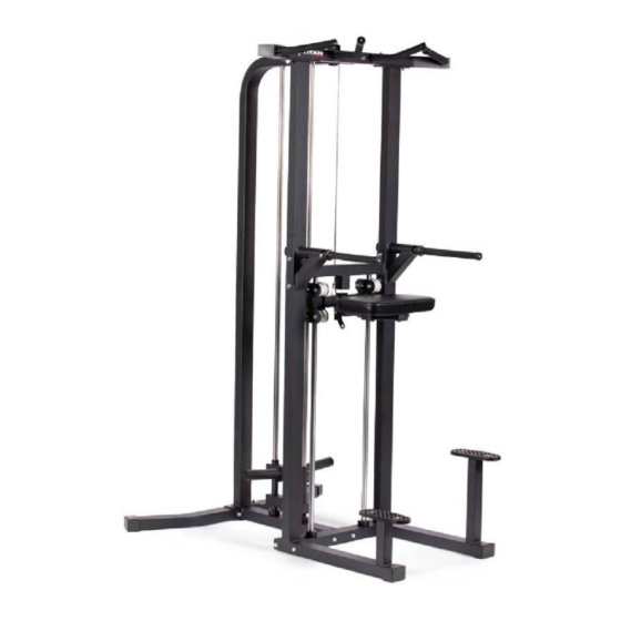
PLATE-LOADED ASSISTED
PULL-UP AND DIP MACHINE
ASSTPULLDP
401482
Operator's Manual
Read the Operator's Manual entirely. When you see this
symbol, the subsequent instructions and warnings are
serious follow without exception. Your life and the lives
of others depend on it!
Advertisement

Related Manuals for Titan Fitness ASSTPULLDP


Summary of Contents for Titan Fitness ASSTPULLDP
- Page 1 PLATE-LOADED ASSISTED PULL-UP AND DIP MACHINE ASSTPULLDP 401482 Operator’s Manual Read the Operator’s Manual entirely. When you see this symbol, the subsequent instructions and warnings are serious follow without exception. Your life and the lives of others depend on it!
- Page 2 PARTS DIAGRAM / EXPLODED VIEW...
- Page 3 DESCRIPTION TOP CROSS FRAME LOWER CROSS FRAME RIGHT UPRIGHT FRAME LIGHT UPRIGHT FRAME REAR BASE FRAME REAR CROSS FRAME FRONT BASE FRAME SLIDING FRAME WEIGHT PLATE SUPPORTER (10) FIXING FRAME (11) GUIDE ROD (12) MAIN FRAME (13) WEIGHT PLATE HOLDER (14) SLIDING ROD (15)
- Page 4 ASSEMBLY INSTRUCTIONS STEP 1 1. CONNECT REAR BASE FRAME (5), REAR CROSS FRAME (6) and FRONT BASE FRAME (7), using FLAT WASHER Φ11*Φ20*2 (60), NUT M10 (55), and HEX BOLT M10*95 (61). 2. Insert the HEX BOLT M10*70 (65) from the bottom of REAR BASE FRAME (5). Insert the GUIDE ROD (11) through the WEIGHT PLATE SUPPORTER (9), and RUBBER CUSHION (39) into the REAR CROSS FRAME (6) and MAIN FRAME (12), fixing by FLAT WASHER Φ10.5*Φ30*2.5 (49), and HEX BOLT M10*25(50).
- Page 5 ASSEMBLY INSTRUCTIONS STEP 2 1. Connect REAR CROSS FRAME (6) and FRONT BASE FRAME (7), using FLAT WASHER Φ11*Φ20*2 (60), NUT M10(55), and HEX BOLT M10*95(61). 2. Connect RIGHT UPRIGHT FRAME (3), LEFT UPRIGHT FRAME (4) and FRONT BASE FRAME (7), using FLAT WASHER Φ11*Φ20*2 (60), NUT M10(55), and HEX BOLT M10*95 (61).
- Page 6 ASSEMBLY INSTRUCTIONS STEP 3 1. Insert the SLIDING ROD (14) through the SLIDING FRAME (8), and RUBBER CUSHION (39) into FRONT BASE FRAME (7) and LOWER CROSS FRAME (2), fixing FLAT WASHER Φ11*Φ20*2 (60), NUT M10(55), and HEX BOLT M10*95(61). Then fixing SLIDING ROD (14) on the LOWER CROSS FRAME (2), using FLAT WASHER Φ10.5*Φ30*2.5 (49), and HEX BOLT M10*25(50).
- Page 7 ASSEMBLY INSTRUCTIONS STEP 4 1. Install the WEIGHT PLATE HOLDER (13) on WEIGHT PLATE SUPPORTER (9) as is shown, using FLAT WASHER Φ11*Φ20*2 (60), NUT M10(55), and HEX BOLT M10*95 (61).
- Page 8 ASSEMBLY INSTRUCTIONS STEP 5 1. Remove the NUT M10 (55) and PULLEY, after the cables assembly is installed, reinstall the pulley and tighter the NUT M10(55). SAFETY HOOK (48) are attached to both ends of the cables, then fixing on the SLIDING FRAME (8) and WEIGHT PLATE SUPPORTER (9).
- Page 9 FULL PARTS LIST / EXPLODED VIEW...
- Page 10 FULL PARTS LIST / EXPLODED VIEW KEY BOX DESCRIPTION QTY KEY BOX DESCRIPTION (37) 1&2 TOP CROSS FRAME Φ25 END CAP (38) 1&2 LOWER CROSS FRAME Φ25 DECORATIVE RING BUFFERED WASHER (39) RIGHT UPRIGHT FRAME Φ55*Φ25*25 SLIDING SLEEVE (40) LIGHT UPRIGHT FRAME Φ35.50*Φ26*39 RUBBER BUMPER (41)
- Page 11 SPACER BUSHING (23) (59) NUT M6 Φ18*Φ10.2*9.5 SPACER BUSH (24) (60) FLAT WASHER Φ11*Φ20*2 Ф21*Ф10.2*9.8 (25) (61) ADJUSTING SHAFT Φ10*86 HEX BOLT M10*95 ROTATING SHAFT (26) (62) HEX BOLT M10*70 Φ12*89*M8 (27) (63) Φ25 WHEEL HEX BOLT M10*90 (28) (64) END CAP 50*50*2.5 HEX BOLT M10*75 (29)
- Page 12 ACKNOWLEDGEMENT OF RISK AND RELEASE OF LIABILITY The use of any equipment, including this one, involves the potential risk of injury. Apart from any warranty claim that might be presented for a claimed defect in material or workmanship of the product, you accept and assume full responsibility for any and all injuries, damages (both economic and non-economic), and losses of any type, which may occur, and you fully and forever release and discharge Titan, its insurers, employees, officers, directors, associates, and agents from any and all claims, demands, damages,...
- Page 13 NEED HELP? CONTACT US FIRST. 1-888-410-1503 info@titan.fitness www.titan.fitness © 2021 Titan Brands...
Need help?
Do you have a question about the ASSTPULLDP and is the answer not in the manual?
Questions and answers