Advertisement
Quick Links
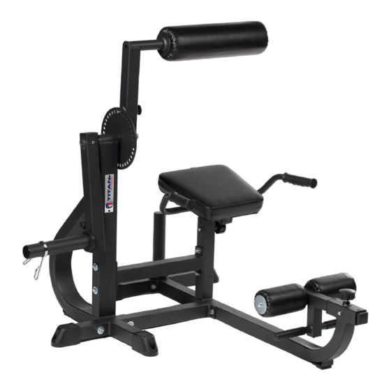
SEATED AB / BACK EXTENSION MACHINE
ABBACK
400991
Operator's Manual
Read the Operator's Manual entirely. When you see this
symbol, the subsequent instructions and warnings are
serious follow without exception. Your life and the lives
of others depend on it!
Cover photo may show optional equipment not supplied
with standard unit. For an Operator's Manual and Decal
Kit in French or Spanish Language, please see your dealer.
Advertisement

Related Manuals for Titan Fitness ABBACK


Summary of Contents for Titan Fitness ABBACK
- Page 1 SEATED AB / BACK EXTENSION MACHINE ABBACK 400991 Operator’s Manual Read the Operator’s Manual entirely. When you see this symbol, the subsequent instructions and warnings are serious follow without exception. Your life and the lives of others depend on it! Cover photo may show optional equipment not supplied with standard unit.
- Page 2 PARTS DIAGRAM / EXPLODED VIEW...
- Page 3 PARTS DIAGRAM / EXPLODED VIEW DESCRIPTION DESCRIPTION COPPER SLEEVE (26) ACROSS FOOT FRAME 38*32*25.2*18 (27) FLAT WASHER 10.5*30*2.5 SUPPORT FRAME (28) FOAM 125*39*450 CROSS SUPPORT FRAME (29) FOAM WASHER 68.5*9.5*3 FOAM FRAME ADJUSTABLE KNOB (30) CROSS CONNECTION FRAME 45*M18*1.5*54 (31) SLEEVE F50*2-F40 ADJUSTABLE FRAME FRONT HOLDER SLEEVE...
- Page 4 ASSEMBLY INSTRUCTIONS STEP 1: Using the HEX HEAD BOLT M10*70 (42) through FLAT WASHER 10.5*30*2.5 (27) and CROSS SUPPORT FRAME (2), REAR FOOT FRAME (14), FLAT WASHER 11*20*2 (38), tighten NUT M10 (39). STEP 2: Using HEX HEAD BOLT M10*70 (42) through FLAT WASHER 10.5*30*2.5 (27) to connect ACROSS FOOT FRAME (1) and CROSS SUPPORT FRAME (3) and through FLAT WASHER 11*20*2 (38), screw on NUT M10 (39).
- Page 5 STEP 3: Using HEX HEAD BOLT M10*70 (42) through FLAT WSHER 11*20*2 (38), connect ACROSS FOOT FRAME (1) and SUPPORT FRAME (2) and through FLAT WASHER 10.5*30*2.5 (27), screw on NUT M10 (39). DO NOT TIGHT THE BOLTS. STEP 4: Using HEAX HEAD BOLT M10*90 (40) and HEX HEAD BOLT M10*70 (42) through...
- Page 6 STEP 5: Using FOAM FRAME (4) put on indicator diagram, tighten FLAT WASHER 10.5*30*2.5 (27), HEX HEAD BOLT M10*25 (43), SPRING WASHER 10 (45). STEP 6: Using WEIGHT PLATE HOLDER (12) infix the frame as indicator diagram and install FLAT WASHER 11*20*2 (38), SPRING WAHSER 10 (45), INNER HEX HEAD BOLT M10*25 (50).
- Page 7 STEP 7: Using FLAT WASHER 11*20*2 (38), screw on NUT M10 (39) and HEX HEAD BOLT M10*75* (41), install RIGHT HANDLE FRAME (9) and LEFT HADNLE FRAME (10) on SEAT CUSHION 320*320*60 (8). Using FLAT WASHER 11*20*2 (38), and HEX HEAD BOLT M10*70 (42) and HEX HEAD BOLT M10*25 (43) install SEAT CISHION 320*320*60 (13) on SEAT CUSHION 320*320*60 (8).
- Page 8 STEP 9: Using ADJUSTABLE FRAME (6) and SEAT CUSHION 320*320*6 (8) insert the frame and tighten ADJSUTABLE KNOB 45*M18*1.5*54 (30) and BUTTON HEAD BOLT M8*25 (44). STEP 10: Using CRASH PAD 77*47.5*13 (24) insert the REAR FOOT FRAME and install CLIP SPRING 50*5 (23).
- Page 9 ACKNOWLEDGEMENT OF RISK AND RELEASE OF LIABILITY The use of any equipment, including this one, involves the potential risk of injury. Apart from any warranty claim that might be presented for a claimed defect in material or workmanship of the product, you accept and assume full responsibility for any and all injuries, damages (both economic and non-economic), and losses of any type, which may occur, and you fully and forever release and discharge Titan, its insurers, employees, officers, directors, associates, and agents from any and all claims, demands, damages,...
- Page 10 NEED HELP? CONTACT US FIRST. 1-888-410-1503 info@titan.fitness www.titan.fitness © 2021 Titan Brands...
Need help?
Do you have a question about the ABBACK and is the answer not in the manual?
Questions and answers