Table of Contents
Advertisement
Quick Links
Advertisement
Table of Contents

Related Manuals for BUSCH DOLPHIN VL 0100 A


Summary of Contents for BUSCH DOLPHIN VL 0100 A
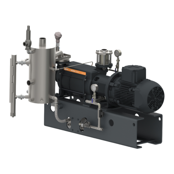
- Page 1 Instruction Manual Supplement DOLPHIN VL Systems ATEX Liquid Ring Vacuum Pumps VL 0100 A, VL 0130 A, VL 0170 A, VL 0180 A, VL 0220 A, VL 0270 A VL 0320 A, VL 0430 A, VL 0510 A, VL 0530 A, VL 0630 A, VL 0750 A, VL 0800 A 0870242202/-_en / Original instructions / Modifications reserved 10/11/2021...
-
Page 2: Table Of Contents
Table of Contents Table of Contents 1 Safety ............................3 2 Product Description ........................4 2.1 Operating Principle ......................7 2.1.1 Once-Through Operation..................7 2.1.2 Partial Recovery (Open Circuit)................7 2.1.3 Total Recovery (Closed Circuit)................7 2.2 Application........................8 2.3 Explanation of ATEX Classification..................8 2.4 Safety concept ......................... -
Page 3: Safety
Safety Prior to handling the machine, this instruction manual should be read and understood. If anything needs to be clarified, please contact your Busch representative. Read this manual carefully before use and keep for future reference. This instruction manual remains valid as long as the customer does not change anything on the product. -
Page 4: Product Description
2 | Product Description Product Description Once through system Partial recovery system LRP NRV OPD TSA1 4 / 36 Instruction Manual Supplement DOLPHIN VL Systems ATEX_EN_en... - Page 5 Product Description | 2 Total recovery system PR PSV OPD FS CLI OPC IV LI Anti-cavitation valve Base frame Compound pressure gauge Cooling liquid inlet Cooling liquid outlet Earth connection Flow switch Suction connection Fresh liquid isolation valve Level indicator Liquid ring vacuum pump Level switch Operating liquid control valve...
- Page 6 2 | Product Description NOTE Illustrations In this instruction manual the illustrations may differ from the machine appearance. NOTE Technical term. In this instruction manual, we consider that the term ‘machine’ refers to the ‘VL System’. NOTE Instruction manual supplement. This document is a supplement to the DOLPHIN LM and LT liquid ring vacuum pump instruction manual whose content remains valid.
-
Page 7: Operating Principle
Product Description | 2 2.1 Operating Principle 2.1.1 Once-Through Operation Gas discharge Process inlet Operating liquid inlet Continuous flow liquid system does not recover the operating liquid which flows out of the separator drain having been separated from the discharge gases which vent sepa- rately. -
Page 8: Application
2 | Product Description 2.2 Application Explosive gases and vapour mixtures can be drawn according to the scope of the Direc- tive ATEX 2014/34/EU. Depending on the equipment, the machine is intended for suction of explosive gases ac- cording to the data given on the nameplate of the machine (NP), see Explanation of AT- EX Classification [► 8]. -
Page 9: Vl System Description
Product Description | 2 2.5 VL System Description In addition to the nameplate of the vacuum pump, a specific nameplate for the VL sys- tem is placed onto the base plate. The VL system description is written on the system’s nameplate. It is defined as in the following example: O = Once through liquid system P = Partial recirculation liquid system... -
Page 10: Total Recovery (Closed Circuit)
3 | Transport At the operating liquid inlet the Y-strainer (ST) prevents particles greater than 0.1 mm entering the vacuum pump. The manual fresh liquid isolation valve (IV) allows the system liquid inlet to be isolated whilst the strainer is cleaned. Operating liquid control valve (OPC) allows the operating liquid flow rate to be regulat- ed for optimum performance of the system. -
Page 11: Storage
Risk of damage to the machine! • Drain the operating liquid from the machine and the system before storage. • Or add an anti-freeze solution. After testing, all Busch DOLPHIN vacuum pumps are vented and drained. Installation 5.1 Installation Conditions WARNING The installation conditions are not respected in an ATEX environment. -
Page 12: Connecting Lines / Pipes
• Make sure that all provided covers, guards, hoods, etc. are mounted. If the machine is installed at an altitude greater than 1000 meters above sea level: • Contact your Busch representative, the motor should be derated or the ambient temperature limited. -
Page 13: Operating Liquid Connection
Installation | 5 CAUTION Restriction of the separator vent. Will cause back pressure and possible separator failure. • The separator vent piping should not be restricted as separator vessel is not pressure rated. • Make sure that the discharged gas will flow without obstruction. Do not shut off or throttle the discharge line or use it as a pressurised air source. - Page 14 5 | Installation Partial recovery system Total recovery system OPD1 Suction connection OPD/ Operating liquid drain OPD1 Operating liquid inlet Operating liquid outlet / overflow Discharge connection Pressure relief vent Connection size: Machine type OPD1 VL 0100 - 0270 A G1 ½...
-
Page 15: Cooling Liquid Connection
Installation | 5 5.2.2 Cooling Liquid Connection • Remove all protective caps before installation. Plate heat exchanger connection Shell and tube heat exchanger connection CLI1 CLO1 CLI/CLI1 Cooling liquid inlet CLO/CLO1 Cooling liquid outlet Machine type CLI1 CLO1 VL 0100 - 0270 A G½... -
Page 16: Pneumatic Valve Air Connection
5 | Installation 5.2.3 Pneumatic Valve Air Connection • Remove all protective caps before installation. AOUT Air inlet AOUT Air outlet/relief • Connection size for both inlet and outlet/relief is G¼. • Air supply required: minimum 2 bar(g), maximum 7 bar(g). •... -
Page 17: Earth Connection
Installation | 5 5.2.4 Earth Connection In order to prevent the machine from creating an electrostatic charge: • Connect to one of the earth connection points (ECP) provided on the base plate. Stud size M10. One through operation system and partial recovery system Total recovery system 5.3 Electrical Connection DANGER... -
Page 18: Wiring Diagram Three-Phase Motor
• Provide an overload protection according to EN 60204-1 for the motor. • Make sure that the motor of the machine will not be affected by electric or electro- magnetic disturbance from the mains; if necessary seek advice from Busch. • Connect the protective earth conductor. -
Page 19: Wiring Diagram Flow Switch
Installation | 5 5.4.1 Wiring Diagram Flow Switch Part no.: Normally open (NO) VL 0100 – 0220 A ► FSW/2063 VL 0270 A ► FSW/2756 VL 0320 – 0750 A ► FSW/2089 Supplier reference: Barksdale BFS-10- …NO-ST-EXI Electrical data: II 1G Ex ia IIB T6 Ga II 1D Ex ia IIIC T85°C Da Operated with a certified switch amplifier for intrinsically safe circuit, maximum values... -
Page 20: Wiring Diagram Pilot Solenoid For Pneumatic Valve
5 | Installation Switch point : For temperature class T4 – 5°K less than temperature class or 20°K less than the liquid boiling point whichever is lowest. For temperature class T5 - maximum of 50°C or 20°K less than the liquid boiling point whichever is lowest. -
Page 21: Commissioning
Commissioning | 6 Commissioning CAUTION During operation the surface of the machine may reach temperatures of more than 70°C. Risk of burns! • Avoid contact with the machine during and directly after operation. NOTICE The machine is running without operating liquid system. Will ruin the machine in short time! •... -
Page 22: Maintenance
Interval Maintenance Work Daily • Check the machine for leaks, in case of leaks have the machine repaired (contact Busch). • Check vacuum pump bearing condition, tempera- ture / audible noise. • Check vacuum pump for audible cavitation noise. Yearly •... -
Page 23: Overhaul
• Decontaminate the machine as much as possible and state the contamination sta- tus in a ‘Declaration of Contamination’. Busch will only accept machines that come with a completely filled in and legally binding signed ‘Declaration of Contamination’ (form downloadable from www.buschvacuum.com). -
Page 24: Spare Parts
Use of non-Busch genuine spare parts. Risk of premature failure! Loss of efficiency and ATEX compliance! • The exclusive use of Busch genuine spare parts and consumables is recommended for the correct functioning of the machine and to validate the warranty. Spare parts Description Part no. -
Page 25: Troubleshooting
VL 0510 A VL 0530 A VL 0630 A VL 0750 A VL 0800 A If other parts are required: • Contact your Busch representative. 11 Troubleshooting Problem Possible Cause Remedy The machine does not start. The motor is not supplied •... - Page 26 The machine runs in the • Check the direction of ro- wrong direction. tation. Defective bearings. • Repair the machine (con- tact Busch). The vacuum pump cavitates • Adjust the anti-cavitation (periodic formation and col- valve. lapsing of steam bubbles in •...
- Page 27 • Seek advice from your lo- cal Busch representative. The operating liquid is too • Adjust cooling liquid flow warm. rate to reduce the tem- perature of the operating (the characteristic curves are liquid.
-
Page 28: Technical Data
12 | Technical Data 12 Technical Data VL 0100 A VL 0180 A VL 0270 A Pumping speed (50Hz / 60Hz)* m³/h 82 / 98 144 / 180 220 / 267 Ultimate pressure (50Hz / 60Hz)* hPa (mbar) 130 / 130 abs. - Page 29 Technical Data | 12 VL 0530 A VL 0800 A Pumping speed (50Hz / 60Hz)* m³/h 440 / 556 722 / 867 Ultimate pressure (50Hz / 60Hz)* hPa (mbar) 130 / 130 abs. Maximum overpressure (50Hz / 60Hz) bar(g) 0.3 / 0.3 Nominal motor rating IEC (50Hz / 60Hz) 11.0 / 15.0 18.5 / 22.0...
- Page 30 12 | Technical Data VL 0130 A VL 0170 A VL 0220 A Pumping speed (50Hz / 60Hz)* m³/h 105 / 128 144 / 165 203 / 232 Ultimate pressure (50Hz / 60Hz)* hPa (mbar) 33 / 33 abs. Maximum overpressure (50Hz / 60Hz) bar(g) 0.3 / 0.3 Nominal motor rating IEC (50Hz / 60Hz)
- Page 31 Technical Data | 12 VL 0320 A VL 0430 A VL 0510 A Pumping speed (50Hz / 60Hz)* m³/h 265 / 320 361 / 426 430 / 510 Ultimate pressure (50Hz / 60Hz)* hPa (mbar) 33 / 33 abs. Maximum overpressure (50Hz / 60Hz) bar(g) 0.3 / 0.3 Nominal motor rating IEC (50Hz / 60Hz)
- Page 32 12 | Technical Data VL 0630 A VL 0750 A Pumping speed (50Hz / 60Hz)* m³/h 500 / 578 617 / 710 Ultimate pressure (50Hz / 60Hz)* hPa (mbar) 33 / 33 abs. Maximum overpressure (50Hz / 60Hz) bar(g) 0.3 / 0.3 Nominal motor rating IEC (50Hz / 60Hz) 15.0 / 22.0 18.5 / 30.0...
-
Page 33: Eu Declaration Of Conformity
13 EU Declaration of Conformity This Declaration of Conformity and the CE-mark affixed to the nameplate are valid for the machine within the Busch scope of delivery. This Declaration of Conformity is issued under the sole responsibility of the manufacturer. - Page 34 Note...
- Page 35 Note...
- Page 36 Busch Vacuum Solutions We shape vacuum for you. Argentina Denmark Malaysia South Africa info@busch.com.ar info@busch.dk busch@busch.com.my info@busch.co.za Australia Finland Mexico Spain sales@busch.com.au info@busch.fi info@busch.com.mx contacto@buschiberica.es Austria France Netherlands Sweden busch@busch.at busch@busch.fr info@busch.nl info@busch.se Bangladesh Germany New Zealand Switzerland sales@busch.com.bd info@busch.de sales@busch.co.nz...
Need help?
Do you have a question about the DOLPHIN VL 0100 A and is the answer not in the manual?
Questions and answers