Table of Contents
Advertisement
Quick Links
Advertisement
Table of Contents

Related Manuals for BUSCH DOLPHIN LR 0110 A


Summary of Contents for BUSCH DOLPHIN LR 0110 A
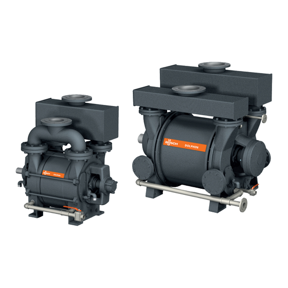
- Page 1 DOLPHIN Liquid Ring Vacuum Pumps LR 0110 A, LR 0140 A, LR 0210 A, LR 0300 A LR 0420 A, LR 0580 A Busch GVT Ltd. Unit A, Westmere Drive Crewe, Cheshire CW1 6ZD United Kingdom 0870237638/-_en/ Original instructions / Modifications reserved...
-
Page 2: Table Of Contents
Table of Contents Table of Contents 1 Safety ............................3 2 Product Description ........................4 2.1 Description of Figures 1 - 4 ....................6 2.2 Operating Principle ......................7 2.3 Application........................8 2.4 Start Controls ........................8 3 Transport ..........................8 4 Storage .............................9 4.1 Short Term (Up to 3 Months) ................... -
Page 3: Safety
Safety Prior to handling the machine, this instruction manual should be read and understood. If anything needs to be clarified, please contact your Busch representative. Read this manual carefully before use and keep for future reference. This instruction manual remains valid as long as the customer does not change anything on the product. -
Page 4: Product Description
2 | Product Description Product Description NOTE Technical term. In this instruction manual, we consider that the term ‘machine’ refers to the ‘vacuum pump’. NOTE Illustrations In this instruction manual the illustrations may differ from the machine appearance. LR 0110 A to LR 0300 A 4 / 32 0870237638_LR0110-0580A_-_IM_en... - Page 5 Product Description | 2 LR 0420 A and LR 0580 A AOUT AOUT Alternative side suction connections* AOUT Alternative side discharge connections** Integral discharge separator Suction connection Operating liquid inlet Operating liquid outlet Discharge connection Shaft seal flushing inlet*** * No manifold, both connections to be used. ** For installations where gas and liquid are discharged to open gutter, both connec- tions open.
-
Page 6: Description Of Figures 1 - 4
2 | Product Description Gas Discharge Suction Discharge Suction Makeup Liquid Discharge Overflow Drain Drain FIGURE 1 FIGURE 2 Gas Discharge Suction Suction Makeup Overflow Gas and Liquid Discharge Drain Drain FIGURE 3 FIGURE 4 Automatic drain valve Compound pressure gauge Gland packing drain Vacuum gauge Heat exchanger... -
Page 7: Operating Principle
Product Description | 2 NOTICE If applying the configuration shown in figure 4. The discharge pressure will rise and lead to an increase in shaft power. • Make sure the cross-sectional area of the gutter is large enough. NOTICE If recirculation of the service liquid is not required. Drainage of the liquid should comply with the appropriate environmental regulations. -
Page 8: Application
Conveying of other media leads to an increased thermal and/or mechanical load on the machine and is permissible only after a consultation with Busch. The machine is intended for the placement in a non-potentially explosive environment. The machine is capable of maintaining ultimate pressure, see Technical Data [► 26]. -
Page 9: Storage
• Drain the operating liquid from the machine and the system before storage. • Or add an anti-freeze solution. After testing, all Busch Dolphin vacuum pumps are vented and drained. 4.1 Short Term (Up to 3 Months) • Seal all apertures with adhesive tape or provided caps. -
Page 10: Installation
• Make sure that the coupling is correctly aligned, see Fitting the Coupling [► 15]. If the machine is installed at an altitude greater than 1000 meters above sea level: • Contact your Busch representative, the motor should be derated or the ambient temperature limited. -
Page 11: Suction Connection
Installation | 5 5.2.1 Suction Connection NOTICE Ingress of foreign objects. Risk of damage to the machine! If the inlet gas contains foreign solid particles: • Install a suitable inlet screen (smaller than 0.2 mm mesh size) upstream of the ma- chine. -
Page 12: Operating Liquid Connection
5 | Installation 5.2.3 Operating Liquid Connection LR 0110 A to LR 0300 A F (OPI) C (OPO) G (SSI) LR 0420 A and LR 0580 A G (SSI) F (OPI) J (ADV) Operating liquid outlet (OPO) Operating liquid inlet (OPI) Shaft seal flush connection (SSI) Clean and drain plug Stuffing box drain plug... -
Page 13: Operating Liquid Settings
Installation | 5 Connection sizes: Machine type LR 0110 A G3" G1" " G¾" G¾" LR 0140 A G3" G1" " G¾" G¾" LR 0210 A G3" " G½" G1" G¾" LR 0300 A G3" " G½" G1" G¾" Machine type LR 0420 A DN100 DN25... - Page 14 5 | Installation LR 0210 A Speed < 200 mbar 200 - 400 mbar 400 - 600 mbar > 600 mbar r/min m³/h m³/h m³/h m³/h 2.64 – 3.30 1.76 – 2.64 1.32 – 1.76 1.10 – 1.32 3.12 – 3.90 2.08 –...
-
Page 15: Fitting The Coupling
Chemical compat- ibility should always be checked by competent personnel before use, particular atten- tion should be paid to elastomer material selection. If in doubt, please consult Busch. 5.4 Fitting the Coupling WARNING Unprotected coupling. -
Page 16: Electrical Connection
• Provide an overload protection according to EN 60204-1 for the motor. • Make sure that the motor of the machine will not be affected by electric or electro- magnetic disturbance from the mains; if necessary seek advice from Busch. • Connect the protective earth conductor. -
Page 17: Commissioning
Commissioning | 6 • Watch the fan wheel of the motor and determine the direction of rotation just before the fan wheel stops. If the rotation of the motor must be changed: • Switch any two of the motor phase wires. For motor wiring and wiring diagrams, please refer to motor manufacturers instruction manuals. -
Page 18: Preventing Cavitation
6 | Commissioning • Make sure that the installation conditions (see Installation Conditions [► 10]) are met. Before operating the machine: • Make sure that the operating liquid level is at the machine shaft centre. • Check the operation of all automatic valves before start up –... -
Page 19: Maintenance
• Check the operating liquid temperature, see Operat- ing Liquid Connection. • Check the machine for liquid leaks - in case of leaks have the machine repaired (contact Busch). If applicable check gland packing leakage rate (20 to 40 drips per minute) and adjust as required. -
Page 20: Overhaul
• Decontaminate the machine as much as possible and state the contamination status in a ‘Declaration of Contamination’. Busch will only accept machines that come with a completely filled in and legally binding signed ‘Declaration of Contamination’ (form downloadable from www.buschvacuum.com). -
Page 21: Spare Parts
Use of non-Busch genuine spare parts. Risk of premature failure! Loss of efficiency! • The exclusive use of Busch genuine spare parts and consumables is recommended for the correct functioning of the machine and to validate the warranty. Spare parts kit Description Part no. -
Page 22: Troubleshooting
Busch). Solid foreign matter has • Remove the solid foreign entered the machine. matter or repair the ma- chine (contact Busch). • Install an inlet screen if necessary. Ice in the machine, the oper- • Carefully warm up the ating liquid has frozen. - Page 23 • Seek advice from your local Busch representa- tive. The operating liquid is too • Reduce the temperature warm or insufficient operat- of the operating liquid or ing liquid.
- Page 24 Wiring Dia- gram Three-Phase Motor [► 16]. Defective bearings. • Repair the machine (con- tact Busch). The vacuum pump cavitates • Consult the chapter Pre- (periodic formation and col- venting Cavitation lapsing of steam bubbles in [► 18].
- Page 25 Troubleshooting | 11 Bearing temperature too Belts are too tight. • Loosen the belts. high. Alignment fail. • Adjust alignment. Bearing lubricated insuffi- • Ensure the bearings are ciently, the grease is dry or lubricated sufficiently. there is too much. The bearings have been in- •...
-
Page 26: Technical Data
Ultimate pressure hPa (mbar) abs. Maximum overpressure bar(g) 0.2 (consult Busch for pressures outside this range) Nominal motor rating 18.5 / 22 / 30 / 45 30 / 37 / 45 / 55 Nominal pump running speed 790 / 980 / 1170 / 1450 790 / 980 / 1170 / 1450 Noise level (EN ISO 2151) - Page 27 Ultimate pressure hPa (mbar) abs. Maximum overpressure bar(g) 0.2 (consult Busch for pressures outside this range) Nominal motor rating 55 / 75 / 110 / 132 75 / 110 / 132 / 185 Nominal pump running speed 500 / 590 / 740 / 790 372 / 472 / 530 / 660 Noise level (EN ISO 2151)
-
Page 28: Eu Declaration Of Conformity
Crewe, Cheshire, CW1 6ZD United Kingdom declares that the machine(s): DOLPHIN LR 0110 A; LR 0140 A; LR 0210 A; LR 0300 A; LR 0420 A; LR 0580 A has (have) been manufactured in accordance with the European Directives: – ‘Machinery’ 2006/42/EC –... - Page 29 Note...
- Page 30 Note...
- Page 31 Note...
- Page 32 Chile Israel Portugal United Arab Emirates info@busch.cl service_sales@busch.co.il busch@busch.pt sales@busch.ae China Italy Romania United Kingdom info@busch-china.com info@busch.it office@buschromania.ro sales@busch.co.uk Colombia Japan Russia info@buschvacuum.co info@busch.co.jp info@busch.ru info@buschusa.com Czech Republic Korea Singapore info@buschvacuum.cz busch@busch.co.kr sales@busch.com.sg www.buschvacuum.com 0870237638/-_en / © Busch GVT Ltd.
Need help?
Do you have a question about the DOLPHIN LR 0110 A and is the answer not in the manual?
Questions and answers