Table of Contents
Advertisement
Quick Links
Instruction Manual Supplement
DOLPHIN VL Systems
Liquid Ring Vacuum Pumps
VL 0100 A, VL 0130 A, VL 0170 A, VL 0180 A, VL 0220 A, VL 0270 A
VL 0320 A, VL 0430 A, VL 0510 A, VL 0530 A, VL 0630 A, VL 0750 A, VL 0800 A
Busch GVT Ltd.
Unit A, Westmere Drive
Crewe, Cheshire CW1 6ZD
United Kingdom
0870233816/-_en / Original instructions / Modifications reserved
08/01/2021
Advertisement
Table of Contents

Related Manuals for BUSCH DOLPHIN VL 0100 A


Summary of Contents for BUSCH DOLPHIN VL 0100 A
- Page 1 VL 0100 A, VL 0130 A, VL 0170 A, VL 0180 A, VL 0220 A, VL 0270 A VL 0320 A, VL 0430 A, VL 0510 A, VL 0530 A, VL 0630 A, VL 0750 A, VL 0800 A Busch GVT Ltd. Unit A, Westmere Drive...
-
Page 2: Table Of Contents
Table of Contents Table of Contents 1 Safety ............................3 2 Product Description ........................4 2.1 Operating Principle ......................6 2.1.1 Once-Through Operation..................7 2.1.2 Partial Recovery (Open Circuit)................7 2.1.3 Total Recovery (Closed Circuit)................7 2.2 VL System Description...................... 7 2.3 Start Controls ........................8 2.4 Control Concept....................... -
Page 3: Safety
Safety Prior to handling the machine, this instruction manual should be read and understood. If anything needs to be clarified, please contact your Busch representative. Read this manual carefully before use and keep for future reference. This instruction manual remains valid as long as the customer does not change anything on the product. -
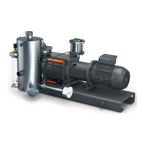
Page 4: Product Description
2 | Product Description Product Description Once through system Partial recovery system OPD TSA 4 / 32 0870233816_VL_Systems_-_IMS_en... - Page 5 Product Description | 2 Total recovery system Anti-cavitation valve Base frame Compound pressure gauge Cooling liquid inlet Cooling liquid outlet Suction connection Fresh liquid isolation valve Level indicator Liquid ring vacuum pump Level switch Operating liquid control valve Operating liquid drain Operating liquid inlet Operating liquid outlet / overflow Operating liquid solenoid isolation valve...
- Page 6 2 | Product Description NOTE Illustrations In this instruction manual the illustrations may differ from the machine appearance. NOTE Technical term. In this instruction manual, we consider that the term ‘machine’ refers to the ‘VL System’. NOTE Instruction manual supplement. This document is a supplement to the Dolphin LM and LT liquid ring vacuum pump in- struction manual whose content remains valid.
-
Page 7: Operating Principle
Product Description | 2 2.1 Operating Principle 2.1.1 Once-Through Operation Gas discharge Process inlet Operating liquid inlet Continuous flow liquid system does not recover the operating liquid which flows out of the separator drain having been separated from the discharge gases which vent separ- ately. -
Page 8: Start Controls
2 | Product Description 2.2 VL System Description The VL system description is written on the system’s nameplate. It is defined as in the following example: O = Once through liquid system P = Partial recirculation liquid system T = Total recirculation liquid system (plate heat exchanger) S = Total recirculation liquid system (shell and tube exchanger) K = Cast iron construction / 316 stainless steel M = 316 stainless steel throughout... -
Page 9: Total Recovery (Closed Circuit)
Product Description | 2 2.4.2 Partial Recovery (Open Circuit) Approximately 50% of the operating liquid is recirculated within the system whilst addi- tional liquid is added via the fresh liquid line to maintain the liquid temperature. The pro- cess gas and operating liquid are discharged from the vacuum pump together into the separator vessel (SV) where they are separated. -
Page 10: Transport
Risk of damage to the machine! • Drain the operating liquid from the machine and the system before storage. • Or add an anti-freeze solution. After testing, all Busch Dolphin vacuum pumps are vented and drained. Installation 5.1 Installation Conditions NOTICE Use of the machine outside of the permitted installation conditions. -
Page 11: Connecting Lines / Pipes
• Make sure that all provided covers, guards, hoods, etc. are mounted. If the machine is installed at an altitude greater than 1000 meters above sea level: • Contact your Busch representative, the motor should be derated or the ambient temperature limited. - Page 12 5 | Installation Dolphin VL 0100-0800 A Partial recovery Dolphin VL 0100-0800 A Total recovery - Plate heat exchanger 12 / 32 0870233816_VL_Systems_-_IMS_en...
- Page 13 Installation | 5 OPD CLI Dolphin VL 0100-0800 A Total recovery - Shell and tube heat exchanger CLO1 CLI1 OPD1 Connection size: Machine type OUT OPO OPI OPD CLO CLI OPD1 CLI1 CLO VL 0100 - 0270 A G1 1/2 R1 ½...
-
Page 14: Electrical Connection
• Provide an overload protection according to EN 60204-1 for the motor. • Make sure that the motor of the machine will not be affected by electric or electro- magnetic disturbance from the mains; if necessary seek advice from Busch. • Connect the protective earth conductor. -
Page 15: Electrical Connection Of The Monitoring Devices
Installation | 5 5.4 Electrical Connection of the Monitoring Devices NOTE The accessories below are considered as standard. If other specific components should be used, refer to the instruction manual of the ac- cessory in question. 5.4.1 Wiring Diagram Solenoid Valve Part no. : VZS/0.50/DW/M/V1 Supplier reference : Model CLO3EB13T Pilot Diaphragm... -
Page 16: Commissioning
6 | Commissioning Commissioning CAUTION During operation the surface of the machine may reach temperatures of more than 70°C. Risk of burns! • Avoid contact with the machine during and directly after operation. NOTICE The machine is running without operating liquid system. Will ruin the machine in short time! •... -
Page 17: Maintenance
Interval Maintenance work Monthly • Check the machine for liquid leaks - in case of leaks have the machine repaired (contact Busch). • Check gauges are functioning – replace if damaged. Yearly • Clean Y-strainer. • Clean inlet screen if installed. -
Page 18: Overhaul
• Decontaminate the machine as much as possible and state the contamination status in a ‘Declaration of Contamination’. Busch will only accept machines that come with a completely filled in and legally binding signed ‘Declaration of Contamination’ (form downloadable from www.buschvacuum.com). -
Page 19: Spare Parts
Use of non-Busch genuine spare parts. Risk of premature failure! Loss of efficiency! • The exclusive use of Busch genuine spare parts and consumables is recommended for the correct functioning of the machine and to validate the warranty. Spare parts Description Part no. -
Page 20: Troubleshooting
Busch). Solid foreign matter has • Remove the solid foreign entered the machine. matter or repair the ma- chine (contact Busch). • Install an inlet screen if necessary. Ice in the machine, the oper- • Carefully warm up the ating liquid has frozen. - Page 21 • Seek advice from your local Busch representa- tive. The operating liquid is too • Adjust cooling liquid flow warm. rate to reduce the tem-...
- Page 22 11 | Troubleshooting Separator liquid level not Partial blockage in the liquid • Remove the blockage. maintained. outlet/overflow line. Control switch operation. • Check switch to solenoid valve control. • Check switch operation – replace if damaged. • Check solenoid valve op- eration –...
-
Page 23: Technical Data
Technical Data | 12 12 Technical Data VL 0100 A VL 0180 A VL 0270 A Pumping speed (50Hz / 60Hz)* m³/h 82 / 98 144 / 180 220 / 267 Ultimate pressure (50Hz / 60Hz)* hPa (mbar) 130 / 130 abs. - Page 24 12 | Technical Data VL 0530 A VL 0800 A Pumping speed (50Hz / 60Hz)* m³/h 440 / 556 722 / 867 Ultimate pressure (50Hz / 60Hz)* hPa (mbar) 130 / 130 abs. Maximum overpressure (50Hz / 60Hz) bar(g) 0.5 / 0.5 Nominal motor rating IEC (50Hz / 60Hz) 11.0 / 15.0 18.5 / 22.0...
- Page 25 Technical Data | 12 VL 0130 A VL 0170 A VL 0220 A Pumping speed (50Hz / 60Hz)* m³/h 105 / 128 144 / 165 203 / 232 Ultimate pressure (50Hz / 60Hz)* hPa (mbar) 33 / 33 abs. Maximum overpressure (50Hz / 60Hz) bar(g) 0.5 / 0.5 Nominal motor rating IEC (50Hz / 60Hz)
- Page 26 12 | Technical Data VL 0320 A VL 0430 A VL 0510 A Pumping speed (50Hz / 60Hz)* m³/h 265 / 320 361 / 426 430 / 510 Ultimate pressure (50Hz / 60Hz)* hPa (mbar) 33 / 33 abs. Maximum overpressure (50Hz / 60Hz) bar(g) 0.5 / 0.5 Nominal motor rating IEC (50Hz / 60Hz)
- Page 27 Technical Data | 12 VL 0630 A VL 0750 A Pumping speed (50Hz / 60Hz)* m³/h 500 / 578 617 / 710 Ultimate pressure (50Hz / 60Hz)* hPa (mbar) 33 / 33 abs. Maximum overpressure (50Hz / 60Hz) bar(g) 0.5 / 0.5 Nominal motor rating IEC (50Hz / 60Hz) 15.0 / 22.0 18.5 / 30.0...
-
Page 28: Eu Declaration Of Conformity
United Kingdom declares that the machine(s): DOLPHIN VL 0100 A; VL 0130 A; VL 0170 A; VL 0180 A; VL 0220 A; VL 0270 A; VL 0320 A; VL 0430 A; VL 0510 A; VL 0530 A; VL 0630 A; VL 0750 A; VL 0800 A has (have) been manufactured in accordance with the European Directives: –... - Page 29 Note...
- Page 30 Note...
- Page 31 Note...
- Page 32 Chile Israel Portugal United Arab Emirates info@busch.cl service_sales@busch.co.il busch@busch.pt sales@busch.ae China Italy Romania United Kingdom info@busch-china.com info@busch.it office@buschromania.ro sales@busch.co.uk Colombia Japan Russia info@buschvacuum.co info@busch.co.jp info@busch.ru info@buschusa.com Czech Republic Korea Singapore info@buschvacuum.cz busch@busch.co.kr sales@busch.com.sg www.buschvacuum.com 0870233816/-_en / © Busch GVT Ltd.
Need help?
Do you have a question about the DOLPHIN VL 0100 A and is the answer not in the manual?
Questions and answers