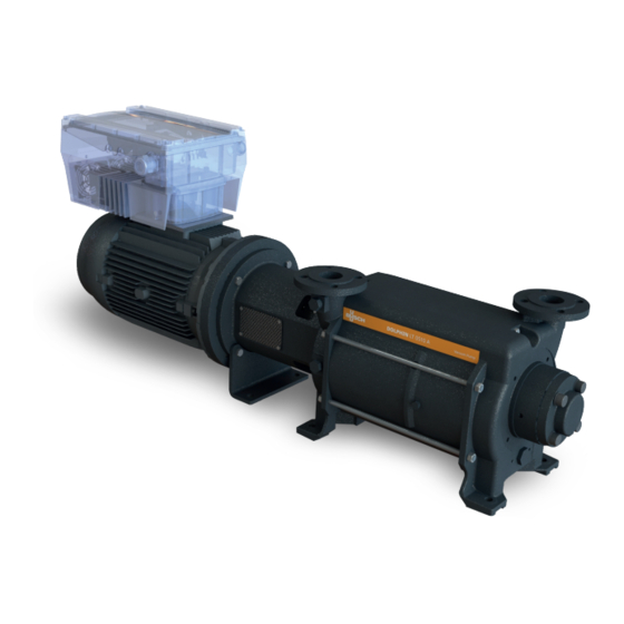
BUSCH DOLPHIN LM 0530 A Retrofit Instructions
Variable-frequency drive installation
Hide thumbs
Also See for DOLPHIN LM 0530 A:
- Instruction manual (28 pages) ,
- Instruction manual (40 pages)

Related Manuals for BUSCH DOLPHIN LM 0530 A


Summary of Contents for BUSCH DOLPHIN LM 0530 A
- Page 1 Retrofit Instructions DOLPHIN Variable-Frequency Drive Installation LM 0530 A, LM 0800 A LT 0320 A, LT 0430 A, LT 0510 A, LT 0630 A 0870224006/-0001_en / Original instructions / Modifications reserved 16/09/2021...
-
Page 2: Table Of Contents
Table of Contents Table of Contents 1 Safety ............................3 2 Introduction ..........................3 3 Retrofit Kit Description ......................4 3.1 Scope of Delivery ......................4 3.1.1 Variable-Frequency Drive without Motor............... 4 3.1.2 Variable-Frequency Drive with Motor..............5 3.2 Motor Compatibility ......................8 4 Transport ..........................8 5 Storage .............................9 6 Installation..........................9... -
Page 3: Safety
Safety Prior to handling the machine, this instruction manual should be read and understood. If anything needs to be clarified, please contact your Busch representative. Read this manual carefully before use and keep for future reference. This instruction manual remains valid as long as the customer does not change anything on the product. -
Page 4: Retrofit Kit Description
3 | Retrofit Kit Description Retrofit Kit Description 3.1 Scope of Delivery Different retrofit kit levels are available and mainly depends on the motor type previously fitted on the machine. The retrofit kit without motor is only intended for machines having a compatible motor with the variable-frequency drive included in this kit, see Motor Compatibility [► 8]. -
Page 5: Variable-Frequency Drive With Motor
Retrofit Kit Description | 3 – Inverter retrofit kit 22 kW (to suit DOLPHIN LT 0630 A, LM 0800 A) Kit number: 0999 700 456 Pos. Part Part no. Variable-frequency drive 0643 700 408 Adapter Plate 0360 700 450 Countersunk screw 906.0MM /006/020 Hex head screw 914.0MM/008/012... - Page 6 3 | Retrofit Kit Description 11kW & 15kW Kits Pos. 550 Pos. 450 Pos. 402 Pos. 300 Pos. 400 Pos. 401 Pos. 403 – Inverter & Motor retrofit kit 15kW (to suit DOLPHIN LT 0430 A, LT 0510 A, LM 0530 A). Kit number: 0999 700 463 Pos.
- Page 7 Retrofit Kit Description | 3 22kW Kit Pos. 550 Pos. 401 Pos. 300 Pos. 400 Pos. 403 Pos. 404 Pos. 402 – Inverter & Motor retrofit kit 22kW (to suit DOLPHIN LT 0630 A, LM 0800 A) Kit number: 0999 700 464 Pos.
-
Page 8: Motor Compatibility
• Do not walk, stand or work under suspended loads. Motor + VFD weight (approx.): DOLPHIN LT 0320 A = 134kg DOLPHIN LM 0530 A, LT 0430 A or LT 0510 A = 180kg DOLPIN LT 0630 A or LM 0800 A = 195kg VFD weight: 21 kg •... -
Page 9: Storage
Storage | 5 Storage NOTICE Long storage time. Risk of damage to the variable-frequency drive! Due to a long storage time the capacitors of the variable-frequency drive can lose effi- ciency because of electrochemical processes. In worst case it can lead to a short circuit and therefore to a damage to the variable-frequency drive. -
Page 10: Variable-Frequency Drive Installation Location
6 | Installation 6.1.1 Variable-Frequency Drive Installation Location • Make sure that the variable-frequency drive is located as below: 6.1.2 Line Protection • Make sure that the cross-section of the supply line is designed according to the trans- fer category and the maximum permitted current. The contractor commissioning the device must ensure protection for the power line. -
Page 11: Preventing Electromagnetic Interferences
Installation | 6 Altitude of the installation If the machine is installed at an altitude greater than 1000 location meters above sea level: *Contact your Bush representative, the motor should be derated or the ambient temperature limited. Ambient temperature Inverter allowable -25 °C to +50 °C. Relative humidity ≤... -
Page 12: Variable-Frequency Drive Installation
6 | Installation 6.2 Variable-Frequency Drive Installation NOTICE Sealing not correctly mounted. Loss of the protection class! • Make sure during assembly tasks to correctly mount all sealing. • Replace any worn or damaged seal. 6.2.1 Dismantle the Motor Terminal Box •... -
Page 13: Mount Variable-Frequency Drive
Installation | 6 • Unscrew the temperature wire block from motor. • Mount the adapter plate (pos. 2) with the flat gasket (pos. 6) and the four screws (T40 M6x16) (pos. 3) (torque: 25NM). 6.2.3 Mount Variable-Frequency Drive Pos. 7 pos. -
Page 14: Connect Variable-Frequency Drive To Motor
6 | Installation 6.2.4 Connect Variable-Frequency Drive to Motor • Connect the variable-frequency drive to the motor by using the wiring materials (pos. 7) delivered in the retrofit kit as follows: Motor connection assignment Connect all cables to the following connections: (3) "Mains terminal [X1]"... -
Page 15: Motor & Coupling Installation
Installation | 6 Motor temperature switch connection Terminal no. Designation Assignment Connection temp. switch (+) Connection temp. switch (-) • Mount the cover on the housing of the variable-frequency drive with the four screws to a torque of 4 Nm. •... -
Page 16: Electrical Connection
6 | Installation 6.4 Electrical Connection DANGER Risk of death due to electrical shock! Death or serious injury! • Be sure that the power supply provides the correct voltage and is designed for the re- quired current. • Use suitable circuit breakers with the prescribed nominal current between the mains and drive controller. - Page 17 Installation | 6 3 x 400 VAC terminal assignment Terminal no. Designation Assignment Mains phase 1 Mains phase 2 Mains phase 3 Earth connection NOTICE Incorrect direction of rotation. Risk of damage to the machine! • Operation in the wrong direction of rotation can destroy the machine in a short time! Prior to start-up, ensure that the machine is operated in the right direction.
-
Page 18: Commissioning
LT 0510 A LT 0630 A Remote speed control and parametrisation are only possible via the remote control and the PC-Software. Contact your Busch representative for more information. NOTICE Frequent starts and stops by connecting and disconnecting from the power supply. -
Page 19: Troubleshooting
• Check the LED on the frequency drive (VFD) is de- variable-frequency drive fective. display, if red, it is faulty (contact Busch or read er- ror with software). En. HW has not been • Using a jumper cable connected. from terminal relay box X5 - 24V Out to En. -
Page 20: Led Flash Codes
8 | Troubleshooting 8.1 LED Flash Codes When an error occurs, the LEDs on the variable-frequency drive display a flashing code that allows the errors to be diagnosed. The following table contains an overview: Red LED Green LED State Boot loader active (flashing in turn) Ready for operation (activate En_HW for operation) Operation / ready Warning... -
Page 21: Technical Data
Technical Data | 9 Technical Data Below additional technical data once the variable-frequency drive has been installed on the motor. The technical datas of the machine in the original instruction manual remain valid after the retrofitting. LM 0530-0800 A with VFD - LT 0320-0630 A with VFD Allowed frequency range 34 –... - Page 22 Note...
- Page 23 Note...
- Page 24 Busch Vacuum Solutions We shape vacuum for you. Argentina Denmark Malaysia South Africa info@busch.com.ar info@busch.dk busch@busch.com.my info@busch.co.za Australia Finland Mexico Spain sales@busch.com.au info@busch.fi info@busch.com.mx contacto@buschiberica.es Austria France Netherlands Sweden busch@busch.at busch@busch.fr info@busch.nl info@busch.se Bangladesh Germany New Zealand Switzerland sales@busch.com.bd info@busch.de sales@busch.co.nz...