
Related Manuals for BUSCH Dolphin LX 0030 A


Summary of Contents for BUSCH Dolphin LX 0030 A
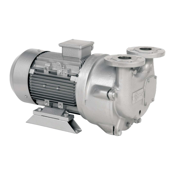
- Page 1 Installation and Operating Instructions Vacuum Pumps Dolphin LX 0030-0430 A Busch GVT Ltd. The Forge Forge Lane Congleton Cheshire CW12 4HG. England 0870151932 / 091006 / Original instructions / Modifications reserved...
-
Page 2: Table Of Contents
Technical Data......18 Busch – All over the World in Industry ....19... -
Page 3: Product Description
The vacuum pump may only be used as contractually agreed with impeller blades with each revolution. Busch. The conveyed medium, the operating liquid and the tempera- The operating liquid also absorbs the heat of compression and conden- ture ranges thereof may not be changed without written consent of sation (when conveying saturated media). -
Page 4: Safety
Disregard of this safety note may lead to accidents with minor inju- VCI-products may attack the surfaces of plastics and elastomers. Seek ries or property damage. advice from your local packaging dealer! Busch uses CORTEC VCI 126 R film for the overseas packaging of large equipment. Noise Emission ●... -
Page 5: Installation And Commissioning
The vacuum relief valve can either be installed in the suction line or on Installation and the housing of the vacuum pump. The gas supply line of the vacuum Commissioning relief valve is usually connected to the liquid separator. Alternatively ambient air can be used to limit the vacuum. -
Page 6: Once Through Operation / No Recovery
(=Li) Level indicator Alternative tank with float valve: (=Pi) Compound (vacuum & pressure) gauge Pressure gauge (=Ti) Thermometer Temperature sensor to r Liquid discharge Connection for operating liquid Suction pipe connection Discharge pipe connection Drain (liquid separator) Drain (pump) Connection for circulation liquid Once Through Operation / No Recovery Partial Recovery The operating liquid is taken directly from a main supply to... -
Page 7: Closed Circuit Cooling / Total Recovery
Circuit diagram: Version with top liquid separator: Alternative thermostatically controlled operating liquid temperature: Circuit diagram: Closed Circuit Cooling / Total Recovery This arrangement provides for total recirculation of the operating liq- uid. A heat exchanger is added to remove the heat of compression, friction and condensation from the operating liquid before it is re-intro- duced back into the vacuum pump. -
Page 8: Suction Connection
Seek advice from your Busch representative! - IEC 364 or CENELEC HD 384 or DIN VDE 0100, respectively,... -
Page 9: Operation Notes
The vacuum pump may only be used as contractually agreed with the required suction capacity (or volume flow) is achieved. The regulat- Busch. The conveyed medium, the operating liquid and the tempera- ing valve shall be locked in this position. -
Page 10: Maintenance
Overhaul Vibration should be less than 5.5 mm/s RMS when measured in Busch service will only accept vacuum pumps that come with a com- the axial, vertical radial and vertical horizontal planes on the bear- pletely filled in and legally binding signed “Declaration of Contamina- ing housing. -
Page 11: Spare Parts
● Dispose of the vacuum pump as scrap metal Spare Parts When ordering spare parts from Busch please quote the following: - Pump type / model number - Pump serial number - Pump ID number... -
Page 12: Troubleshooting
Long suction, discharge or pressure line with Use larger diameter too small diameter Internal parts are worn or damaged Repair the vacuum pump (Busch service) The gas conveyed by the vacuum pump smells Process components evaporating under vac- Check the process, if applicable... - Page 13 Try to turn the drive motor with the vacuum pump by hand If the vacuum pump is blocked: Repair the vacuum pump (Busch service) The drive motor is defective Replace the drive motor (Busch service) The vacuum pump is blocked...
- Page 14 Ambient temperature too high Observe the permitted ambient temperatures Temperature of the inlet gas too high Observe the permitted temperatures for the inlet gas Insufficient gas transfer Mains frequency or voltage outside tolerance Provide a more stable power supply range Partial clogging of filters or screens Remove the clogging Partial clogging in the suction, discharge or...
-
Page 15: Ec-Declaration Of Conformity
Note: This Declaration of Conformity and the -mark affixed to the nameplate are valid for the vacuum pump within the Busch-scope of delivery. When this vacuum pump is integrated into a superordinate machinery the manufacturer of the superordinate machinery (this can be the operating company, too) must conduct the conformity assessment process acc. -
Page 16: Sectional Drawings And Spare Parts Lists
Sectional Drawings and Spare Parts Lists LX 0030 A to LX 0055 A 106.7 End casing 900.2 Set screw 185.2 Impeller casing 902.0 Stud 230.1 Impeller 903.0 Plug 400.7 Inspection cover gasket 907.0 Adjusting nut 412.0 O-ring 914.0 Cap screw 433.0 Mechanical seal 920.0... -
Page 17: Lx 0110 A To Lx 0430 A
LX 0110 A to LX 0430 A 106.7 End casing 900.1 Set screw 185.2 Impeller casing 900.2 Set screw 230.1 Impeller 902.0 Stud 400.7 Inspection cover gasket 903.0 Plug 412.0 O-ring 903.1 Plug 433.0 Mechanical seal 907.0 Adjusting nut 562.0 Dowel 920.0 Nut (not required on model LX 0110 A) -
Page 18: Technical Data
LX 0430 A 1750 ~198 * Average flow for once through operation. reduce by 50 % for partial recovery. ** Consult Busch GVT for motor power ratings for high discharge pressures. Technical Data LX 0030-0430 A page 18 0870151932 / 091006... -
Page 19: Busch - All Over The World In Industry
Busch – All over the World in Industry www.busch-vacuum.com Australia New Zealand Dr.-Ing. K. Busch GmbH Außenstelle Neuenrade Busch Australia Pty. Ltd. Busch New Zealand Ltd. Breslauer Str. 36 30 Lakeside Drive Unit D, 41 Arrenway Drive 58809 Neuenrade Broadmeadows, Vic. 3047...
Need help?
Do you have a question about the Dolphin LX 0030 A and is the answer not in the manual?
Questions and answers