Advertisement
TF115P-003 RAINTIGHT THERMOSTAT
The PECO
TF115F-003 is a robust commercial thermostat—fully assembled, and ready
®
to use — for plug-in temperature control of ventilation in greenhouses, warehouses and
industrial facilities. The rugged enclosure can be used for cooling or heating in indoor or
outdoor applications. Note: For cooling applications, see Wiring Diagram on page 2.
The PECO
TF115F-003 control, which is housed in the raintight gray plastic enclosure,
®
uses a stainless steel coil as a temperature-sensing bulb.
Maximum sensing element withstand temperature is 145°F (62°C). Maximum temperature
for the plastic enclosure is 140°F (60°C).
INSTALLATION INSTRUCTIONS
Locate the thermostat about four feet (1.2 m) above the floor on a wall in an area with
good ventilation and an average temperature, where it will be responsive to changes in
room temperature. The unit is to be assembled with cover, gasket, and four (4) screws
installed and fully tightened (see Fig. 1). The TF115P-003 enclosure may be mounted
onto a wall or panel surface with #8 or #10 screws.
• With the plug-in inserted to 120 VAC outlet, a heater may be plugged into the series plug
(see Fig. 2) to provide temperature-related operation.
• Power cord is attached to internal leads; default wiring is set for heating.
• Adjustable temperature range is 40° to 110° F (4° to 43° C)
• Temperature Dial: One dial division equals 2°F (1.1° C) (See Fig. 1)
• Cord seal must remain tightened around power cord to maintain rain-tight seal; if removed,
the locking nut must be held stationary while gland nut is fully tightened (see Fig 1, 2)
▲
!
CAUTION! USE 120 VAC ONLY!
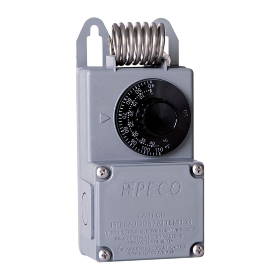
TF115P-003 FRONT PANEL AND SIDE REFERENCE
Sensing bulb
Temperature
40
Dial
Junction
Box
Cover
CAUTION
PRECAUCION / ATTENTION
DISCONNECT POWER BEFORE REMOVING COVER.
DESCONECTE LA ENERGIA ANTES
DE REMOVER LA CUBIERTA.
DEBRANCHER LE COURANT AVANT
DE RETIRER LE COUVERCLE.
Cord
Seal
(Locking nut
and gland
nut)
Power
Cord
Figure 1. TF115P-003. Frontal view
© COPYRIGHT 2019 PECO, INC. ALL RIGHTS RESERVED.
Sensing bulb
Temperature
Dial
Junction
Box
Cover
Knockout
(side)
Cord
Seal
(Locking nut
and gland
nut)
Power
Cord
Series
Figure 2. TF115P-003. Side view
TF115P-003 THERMOSTAT
INSTALLATION GUIDE
▲
WARNING
!
• READ THESE INSTRUCTIONS CAREFULLY BEFORE ATTEMPTING TO INSTALL,
OPERATE OR SERVICE THIS THERMOSTAT. Failure to observe safety information
and comply with instructions could result in PERSONAL INJURY, DEATH AND/OR
PROPERTY DAMAGE.
• Retain these instructions for future reference.
• To prevent overheating or fire, use this control as an operating or regulating
thermostat. ALWAYS USE A BACKUP CONTROL OR ALARM if a control failure could
cause the controlled appliance to overheat or could cause a fire.
• Do not install, use or operate if product appears damaged, the enclosure is cracked or
broken or if the sensor has been bent, crimped or is dirty.
• To avoid potential fire and/or explosion, do not use in potentially flammable or
explosive atmospheres.
• IMPORTANT: Do not impact, dent or use the sensor for support. This will cause
calibration and/or thermostat failure.
PRODUCT SPECIFICATIONS
VAC
INDUCTIVE
FLA
120
4.4
Temperature Control Range:
Differential:
Maximum Ambient Temperature:
Dimensions:
Line cord:
Weight:
OPERATION AND CHECKOUT
Allow one hour or necessary amount of time for the thermostat and system to stabilize for
normal operation. This thermostat is factory calibrated and requires no correction on site.
By default, the TF115P-003 thermostat is wired for heating operation.
To Check Operation:
1. Set Temperature Dial to desired temperature setpoint.
2. Plug the controlled device (e.g., fan) into the series plug (female side of TF115P plug).
3. Plug the TF115P power cord into the wall outlet. Note: Outlet must be 120 VAC.
4. To start operation, rotate Temperature Dial. Wait for the unit to turn on.
Note: For units that are wired for Heating operation (default) rotate the Dial at least
five (5) degrees above the current ambient temperature. For units that are rewired for
Cooling Operation, rotate the Dial at least five (5) degrees below the current ambient
temperature.
5. Return Temperature Dial to the desired temperature setpoint. (The TF115P will
automatically control to desired temperature).
1
RESISTIVE
PILOT
AMPS
DUTY
LRA
26.4
13
125 VA
40° to 110° F (4° to 43° C)
3° F (1.7°C)
140°F (60°C)
2.80"(L) X 2.5" (W) X 7" (H) inches
6 feet, 7-wire, double insulated, 16 AWG,
U.L. Listed, Plug: 3-pole male/female,
120 VAC plug style, American (grounded)
0.88 lbs
P/N 73433 REV 00
Advertisement
Table of Contents

Related Manuals for Peco TF115P-003


Summary of Contents for Peco TF115P-003
- Page 1 The unit is to be assembled with cover, gasket, and four (4) screws installed and fully tightened (see Fig. 1). The TF115P-003 enclosure may be mounted PRODUCT SPECIFICATIONS onto a wall or panel surface with #8 or #10 screws.
- Page 2 TO ENSURE WATER TIGHTNESS, THE GASKET MUST BE RE-INSTALLED UNDER THE JUNCTION BOX COVER. © COPYRIGHT 2019 PECO, INC. ALL RIGHTS RESERVED. P/N 73433 REV 00 PECO is a registered trademark of PECO, Inc. All other trademarks, and/or registered trademarks, are the property of their respective owners.
Need help?
Do you have a question about the TF115P-003 and is the answer not in the manual?
Questions and answers