
Related Manuals for 2N LiftNet


Summary of Contents for 2N LiftNet
- Page 1 ® LiftNet Lift Communicator User Manual Version 1.5.2 www.2n.cz Firmware version 1.5.2...
- Page 2 ® LiftNet product is the holder of the Type certificate of the TÜV SÜD Czech company.
-
Page 3: Table Of Contents
Table of Contents PRODUCT OVERVIEW ................... 7 ........................... 8 RODUCT ESCRIPTION Basic Features ............................8 Basic Description ............................8 System Block Diagram ..........................9 ® ..............10 OMPONENTS AND SSOCIATED RODUCTS ... - Page 4 Electric Installation ............................ 45 – L ....................48 UDIO HAFT Description ..............................48 Before You Start............................49 Mounting..............................49 Electric Installation ............................ 49 CONFIGURATION..................51 LN P ..........................52 ROGRAMMING ...
- Page 5 ........................78 ECHNICAL ARAMETERS Telephone Parameters ..........................78 Other Parameters ............................. 79 SUPPLEMENTARY INFORMATION ..............81 ............................82 EGULATIONS ..........................83 ROUBLESHOOTING FAQ ................................83 ....................84 ENERAL NSTRUCTIONS AND AUTIONS...
-
Page 7: Product Overview
Product Overview ® In this section, we introduce the 2N LiftNet product, outline its application options and highlight the advantages following from its use. Here is what you can find in this section: Product Description ® LiftNet Components and Associated Products... -
Page 8: Product Description
Basic Description ® LiftNet (LN) is a communication system similar to the intercom. The audio units are connected (through a pair of conductors) to a common bus, to which one central unit (CU) is connected. The CU controls the system operation and provides connection to the dispatching office. -
Page 9: System Block Diagram
Product Description System Block Diagram... -
Page 10: Lift Net Components And Associated Products
N® LiftN Net Comp ponents and Ass ociated Products ® 1.2 2 2N ftNet pone ents a and A Assoc ciated roduc stem C Compo onents Caution ® The 2N Lift tNet system m compone ents can be used withi... - Page 11 2N® LiftNet Components and Associated Products Audio unit electronics for lift cars. A robust, metal-encased audio unit, Including loudspeaker and microphone provided with an ALARM button of the (HandsFree). Necessary terminals and prescribed size, including indicators for door opening signal input (not optional).
-
Page 12: Associated Products
2N® LiftNet Components and Associated Products Associated Products 913630E ® LiftManager ® The 2N LiftManager system is intended for remote monitoring, control and ® ® ® communication with 2N LiftNet, 2N EasyTalk and 2N SingleTalk units. Part of the ®... -
Page 13: Upgrade And Innovations
Dispatching centre instructions fixed: for call confirmation press 1, for prolongation press 4, for call termination use 5 or # Call sequencing – corrected according to reality, corresponds to SW 1.3.5 ® Changes for FW 1.3.0 – see 2N LiftNet programming Changes for FW 1.2.0... -
Page 14: Pictograms Used
Used Abbreviations, Terms and Pictograms 1.4 Used Abbreviations, Terms and Pictograms ® LiftNet Central unit of the system, typically shared by multiple lifts in a building Audio unit Voice communication unit for lift communication with the dispatching office or another system unit... -
Page 15: Manual Symbols
Important information for system functionality. Useful information for quick and efficient functionality. Note Routines or advice for efficient use of the device. Future functions The grey marked text in this document specifies the 2N® LiftNet functions that will be supported in the future. -
Page 17: Description And Installation
Description and Installation The section is divided according to system components into the following subsections: PSTN Central Unit GSM Central Unit Lift Car Audio Unit – Universal Lift Car Audio Unit – Compact Audio Unit – Machine Room Audio Unit – Lift Shaft / Car Roof LN Programming Each subsection includes: Component Description... -
Page 18: Pstn Central Unit
PSTN Central Unit 2.1 PSTN Central Unit Description Figure 2.1 Power supply Central Unit Green OK (battery full) LED Indicators Green flashing Battery charging Battery failure Power failure, more than 1 hour of operating time remains Red flashing Power failure, less than 1 hour of operating time remains Red flashing after Audio unit FW upgrade proceeding... -
Page 19: Before You Start
PSTN Central Unit Before You Start CU installation conditions The CU is not designed for outdoor applications. Do not mount the CU onto vibration-producing machines. Install the CU vertically to allow air flow for cooling purposes (never cover the CU with any cloth or install it in another closed box). You may install the CU into the lift switching board unless the temperature exceeds the acceptable limit. -
Page 20: Cu Mounting
PSTN Central Unit Weak and short green flashing The battery is OK and fully charged, you may continue with the installation. If the product was stored for longer period than ½ year, or under temperature exceeding 25 °C proceed according to paragraph b. Caution The product needs to be put in operation after the tape has been removed. - Page 21 ® LiftNet requires the telephone line exclusively for itself. This means that NOT even a system through which the telephone line goes (priority connection, ESS, e.g.) may be connected to this telephone line.
- Page 22 PSTN Central Unit Direct PSTN Connection This is the simplest and most reliable type of connection. High operational costs (flat rate costs) are a drawback of this solution. Telephone line requirements No double or group serial line. The telephone socket including cabling is a property of the telecom company and may not be tampered with.
- Page 23 PSTN Central Unit GSM Gateway Connection (Temporary – Substitutes the GSM CU Version, Part No. 913601) Used wherever no fixed telephone line is available. Requirements The GSM gateway has to be functional even in the case of power outage. The GSM gateway has to recover its function without requiring the PIN. Other Requirements Find a suitable place or use a special (directional) antenna where the GSM signal quality is poor.
-
Page 24: Interruption Of Operation, Battery Maintenance
PSTN Central Unit Interruption of Operation, Battery Maintenance Cautions Never leave the batteries discharged for unnecessarily long periods. If the battery is fully discharged please recharge it as soon as possible. For a detailed description of situations that require your attention due to the state of accumulators during interruption refer to the Maintenance section. -
Page 25: Gsm Central Unit
GSM Central Unit 2.2 GSM Central Unit This product is under preparation. By the time it becomes available, you are recommended to use the PSTN central unit ® in combination with 2N EasyGate. Figure 2.3 GSM Central Unit... -
Page 26: Lift Car Audio Unit - Universal
Lift Car Audio Unit – Universal 2.3 Lift Car Audio Unit – Universal Description The user is not in a direct contact with this Figure 2.4 Lift Car Audio product. Unit – Universal The controls and indicators depend on the lift car control panel type. -
Page 27: Mounting
Lift C Car Audio o Unit – U Universa 5 tightening g strips ounting Main b board m mounting This audio o unit is mo ounted beh ind the lift control pan nel. Typical lly, the pan nel is ready for installa ation as sh own in the... - Page 28 Lift Car Audio Unit – Universal Warnings Leave no gap between the lift control panel and the audio unit surface to avoid acoustic loudspeaker fault and acoustic loudspeaker-microphone feedback. Do not use this type of audio unit in a position other than mounted on a sufficiently large board.
- Page 29 Lift Car Audio Unit – Universal May I use a longer cable with the loudspeaker? Yes, but not with the microphone.
-
Page 30: Electric Installation
Lift C Car Audio o Unit – U Universa Ele ectric I nstalla ation Descri ption o of termin nals, co onnecto rs and j jumpers Figure 2.5 Description of Terminals, onnectors and Jumpers for Lift Car Audio nit – Universal Terminals Connect tors... -
Page 31: Unit
Lift C Car Audio o Unit – U Universa Note f external L LEDs are co onnected to o connector rs 7 and 8, on-board L LEDs 1 nd 2 will no ot be shinin Addres ss Setti The audio o unit addre ess means setting of t... - Page 32 Lift Car Audio Unit – Universal ALARM Button Connection Requirements The ALARM button design (colour, pictogram, button surface, mechanical run) and location have to meet the requirements of the particular installation. Button control Requirements The ALARM button has to be equipped with a normally open (NO) or normally closed (NC) contact that is not connected with any other circuit.
- Page 33 Lift Car Audio Unit – Universal CANCEL Input Connection (Door Contact, Optional) This input helps cancel a rescue request if the lift is fully functional. When the ALARM button is pressed, the system waits for a pre-programmed period of time, which is a little longer than the maximum lift running time.
- Page 34 Lift C Car Audio o Unit – U Universa Indicat tor Con nnection The basic configurat ion providin ng (using a an external source) a sufficient il lumination intensity o of indicatio n elements s is shown i in the figur Figure 2.7 sic Indicator nnection for...
- Page 35 Lift Car Audio Unit – Universal Induction Loop Connection The regulations that apply to communicator installations may require a mandatory loop for persons with defective hearing in the lift cabin. In that case, connect the loop to connector (10) with any polarity. The loop including a 1m long cable can be part of your delivery if agreed.
-
Page 36: Description
Lift C Car Audio o Unit – Compac 4 Lif ft Ca r Aud dio U nit – pact scripti This audio o unit is de signed for lift wall mo ounting. No opening h as to be cu ut for installatio on since the e audio unit... -
Page 37: Before You Start
Lift Car Audio Unit – Compact Before You Start Requirements The lift wall surface must be perfectly flat. The mounting place must comply with applicable regulations (e.g. standard ALARM button elevation and relative distance from other lift buttons). Product Completeness Check Check the product for completeness before installation please: 1 Compact audio unit 1 window with printing... - Page 38 Lift Car Audio Unit – Compact Address Setting The audio unit is set as lift car 1 by default. If you want to change the address, you are recommended to do so before mounting. Audio unit position setting 0–3 with a possibility of inverting CANCEL (4–7) Lift number setting 1–8 Instructions...
-
Page 39: Mounting
Lift C Car Audio o Unit – Compac Mo ounting Just drill h holes into t the lift car wall as ind icated in th he drawing below or a as printed 1 on the au udio unit pa ackage. Th he larger ho ole is inten nded for ca... -
Page 40: Electric Installation
Lift Car Audio Unit – Compact Electric Installation Caution Be sure to connect the wires before wall mounting. The connectors are separable – remove them, connect the wires, tighten the screws and replace the connectors. Connectors Figure 2.12 Lift Car Audio Bus Connector Unit –... - Page 41 Lift Car Audio Unit – Compact CANCEL Input Connection (Door Contact, Optional) This input helps cancel a rescue request if the lift is fully functional. When the ALARM button is pressed, the system waits for a pre-programmed period of time, which is a little longer than the maximum lift running time.
-
Page 42: Mounting Completion
Lift C Car Audio o Unit – Compac ounting g Comp pletion Connect t the wires be efore wall m mounting. T The connec ctors are se eparable – r remove them, con nnect the w wires, tighte en the screw ws and rep place the co onnectors. - Page 43 Lift Car Audio Unit – Compact Mounting Completion – without Rear Access 1. Insert the hex wrench (included in the delivery) in the bottom unit edge hole; turn left about 10 times until it puts up resistance. 2. The window slides down by itself or with little assistance, showing its upper brim.
-
Page 44: Audio Unit - Machine Room
Audio Unit – Machine Room 2.5 Audio Unit – Machine Room Description This audio unit is designed for machine room installation. Compared with the other types, it has some unique features: The audio unit contains a telephone set for good voice communication in a noisy environment (Machine Room audio unit is not equipped with Handsfree function as Shaft audio unit has ). -
Page 45: Before You Start
Audio Unit – Machine Room Operating instructions This unit is used by qualified persons, e.g. lift maintenance stuff. TRIPHONY button activates voice communication between all units with the same lift number. ALARM button can be used to call dispatching office. ALARM button backlight (not requested by standards) allows finding unit in darkness. - Page 46 Audio Unit – Machine Room Connectors (under the side door) Figure 2.15 Audio Unit – Machine Room Connectors Bus connector Lift blocking connector Phone connector Address Setting There two groups of jumpers under the transparent front cover. For their meanings see the printing located directly under them.
- Page 47 Audio Unit – Machine Room Cautions Connection to different, e.g. higher-voltage, cables leads to damage or destruction of the audio unit. Unit is powered via 2-wire bus from the Central Unit. Unplugging of the bus from the CU causes switching of the unit. Telephone connection Use the telephone set including the cable with telephone terminals that are part of the audio unit delivery.
-
Page 48: Audio Unit - Lift Shaft / Car Roof
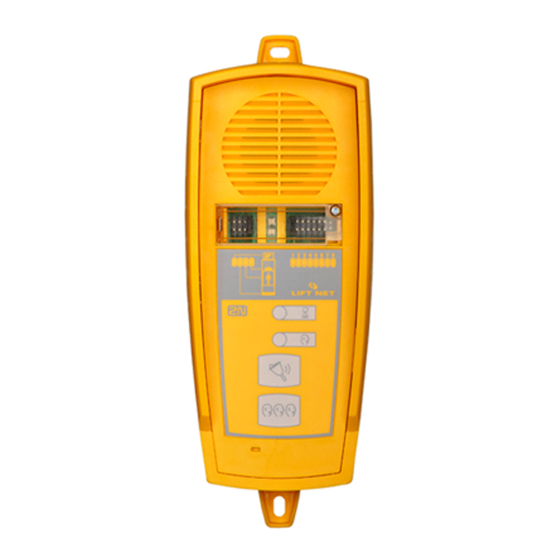
Audio Unit – Lift Shaft / Car Roof 2.6 Audio Unit – Lift Shaft / Car Roof Description This audio unit is designed for installation on the lift shaft bottom or lift cabin roof, or similar places where communication is needed during lift maintenance, for example. The audio unit is enclosed in a robust yellow cover. -
Page 49: Before You Start
Audio Unit – Lift Shaft / Car Roof ALARM button backlight (not requested by standards) allows finding unit in darkness. Before You Start Product Completeness Check Check the product for completeness before installation please: 1 audio unit 2 wall dowels 2 dowel screws Requirements No special requirements for this unit type. - Page 50 Audio Unit – Lift Shaft / Car Roof 9. Close the window and tighten the screw. Connection Release the screw on the right-hand side and open the connector cover. There is just one connector – for bus connection. Remove the terminal board from the connector, connect the wires and replace the terminal board.
-
Page 51: Configuration
Configuration This section describes programming of 2N® LiftNet. It is possible to program 2N® LiftNet in three ways. Telephone-Based Programming PSTN Machine Room PC-Based Programming... -
Page 52: Ln Programming
LN Programming 3.1 LN Programming The advantage is that it is only the CU that has to be programmed. Thus, it is unnecessary to re-program the parameters after audio unit replacement. With a multiple-lift system, you just program one CU. The memory is independent of the CU power supply. - Page 53 LN Programming Note You are recommended to change it to secure your equipment against unauthorised access. If you forget your password, contact the manufacturer to recover your data. You have a 5-second timeout by default (or a user-defined limit of 1 to 9 seconds) to enter every character of your password.
-
Page 54: Parameter Chart (Valid For Fw Ver. 1.3.3)
LN Programming Troubleshooting LN fails to respond correctly to DTMF commands, e.g. the programming mode cannot be entered. Today, voice transmission is prevailingly digital, using variable compression algorithms. Therefore, the DTMF signal to be transmitted is often distorted. Moreover, it may, in some cases, be transmitted through the so-called command channel, whose delay may differ from that of the speech channel. - Page 55 LN Programming par. Parameter Name Range Default Note Checking call up to 16 blank memory 1 digits 0 - 9 Checking call up to 16 blank memory 2 digits 0 - 9 If let completely blank, Checking call up to 16 blank memory 3 digits 0 - 9...
- Page 56 LN Programming par. Parameter Name Range Default Note Call confirmation cannot be Mutes the message too. command changed Message muting cannot be command changed Repeat message cannot be command changed DTMF identification cannot be Mutes the message too. command changed Call prolongation cannot be The call is prolonged by the time set in...
- Page 57 (siren) When the call is answered in the machine room, the voice menu will be cancelled. 0: LiftNet identification off (default) 1: LiftNet identification on (incl. shafts and Identification type audio units ID – parameter YY) for ALARM calls 2: LiftNet identification equal to SingleTalk...
- Page 58 29 = “This is communicator” NOTE: 1) User messages from #1 to #10 must be uploaded via ServiceTool application 2) “” = voice message 3) DTMF sequence (2N protocol) blank Format: *X*Y Y *ID(par.974)*checksum # Outgoing message (=1612 sequence after X=1 - Alarm, 2 –...
- Page 59 LN Programming par. Parameter Name Range Default Note 0 = off (checking call is disabled) 1 = on, first checking call in 1 minute 2 = on, first call in 2 hours 3 = on, first call in full period time 4 = on, checking call according to parameter _..986 (Days in week) 981 Checking call...
-
Page 60: Pc-Based Configuration
To upload the user messages and numbers into the 2N LiftNet device, you will need ® the Service Tools utility. To upload your message into the 2N LiftNet device, please follow these three easy steps: Record your messages using your PC’s soundcard and microphone. Save your voice message to the .wav file with these parameters: 8bit, 8 kHz, MONO. -
Page 61: Function And Use
Function and Use ® This section describes the basic and extending functions of the 2N LiftNet product. Here is what you can find in the section: User Instructions Dispatching Centre Instructions Function Description (for Advanced Users) -
Page 62: User Instructions
User Instructions 4.1 User Instructions Audio Unit - Lift Car The lift car audio unit is intended for lay users. Nevertheless, instructions can be placed in the lift car, e.g., to help the people trapped in the lift communicate with the dispatching centre. - Page 63 User Instructions For connection with the lift cabin choose 1. For the machine room choose 2. For the shaft bottom choose 3. And for the cabin roof choose 4. Press 9 for services. Enter the service password. To end the call press 5. Note Number 9 is primarily used for the LN configuration –...
-
Page 64: Dispatching Centre Instructions
Dispatching Centre Instructions 4.2 Dispatching Centre Instructions ALARM Call The process starts upon pressing the ALARM button on any audio unit. After that, the LN calls the dispatching centre (for details see Automatic Dialling). 2. Once the operator answers the call, he or she hears a message identifying the calling lift. - Page 65 Dispatc ching Ce entre Ins tructions Tone D Dialling Contro ol during g Call – – Compl ete List t of Comm mands Where au tomatic dia alling with c confirmatio on is used, it is possibl le to use to one dialling for LN con ntrol during...
-
Page 66: Function Description (For Advanced Users)
Function Description (for Advanced Users) 4.3 Function Description (for Advanced Users) Purpose of Section The purpose of this section is to help technicians solve problems, if any. If the system fails to work properly and a well-trained technician monitoring its operation step by step according to the description included herein gets to a point where the description and reality are in contradiction, he or she describes the contradiction, thus facilitating troubleshooting. -
Page 67: Triphony
Function Description (for Advanced Users) Triphony Triphony provides interconnection of audio units. This mode can be activated by pressing the TRIPHONY button in the machine room (see the preceding subsection), in the lift shaft or on the lift car roof (audio units No. 913612E). This mode features a different setting of the automatic HandsFree mode. -
Page 68: Call Sequencing
Function Description (for Advanced Users) Call Sequencing If another request arises during communication, the calls are queued. Calls have different priorities – ALARM calls have the highest one. Therefore, the ALARM call suspends any lower-priority call (the checking call, e.g.). Calls with identical priorities are queued and processed one after another. -
Page 69: Automatic Dialling Of Multiple Numbers With Confirmation
Function Description (for Advanced Users) Automatic Dialling of Multiple Numbers with Confirmation Up to 6 telephone numbers including repetitions can be stored for dispatching office calling. LN then tries to call all the numbers stored. To confirm successful calls, LN uses tone dialling (DTMF). -
Page 70: Automatic Redialling Of Multiple Numbers Without Confirmation
Function Description (for Advanced Users) Evaluation of Situations during Automatic Audible Dialling with Confirmation Situation LN Activity Busy tone after number LN hangs up and dials the next number in the dialling end sequence. LN waits for a pre-set period of time (see Parameter Call or silence 913). -
Page 71: Automatic Call Receiving
Automatic Call Receiving ® If equipped with a PC with the 2N LiftManager application, the dispatching centre receives calls automatically. It identifies the calling lifts and types of calls (ALARM, checking, and automatic failure report). -
Page 72: Call End (Outgoing / Incoming Calls)
Function Description (for Advanced Users) the lift address) is under preparation. Checking call Identification of a checking call Rescue has been done. Confirmation of emergency signalling end More audio units are waiting Announcement of an emergency status in for connection. (an)other lift(s) Call End (Outgoing / Incoming Calls) A call is terminated (line hang-up occurs) if any of the following cases happens:... -
Page 73: Maintenance
Maintenance ® This section described the 2N LiftNet product maintenance procedures. Here is what you can find in this section: Battery Maintenance Firmware Upgrade... -
Page 74: Battery Maintenance
Battery Maintenance 5.1 Battery Maintenance First put the accumulators in operation as described in the Description and Installation section (PSTN Central Unit, Before You Start). Also, pay attention to them whenever the operation is interrupted and during replacement. The basic rule is as follows: Warnings Never leave the batteries discharged for unnecessarily long periods. -
Page 75: Battery Pack Replacement
Battery Maintenance batteries will discharge. Do not forget to recharge them as soon as possible, or – preferably – disconnect the green connector if you do not need to have the system on. Battery Pack Replacement Battery Pack Service Life The warranty period does not apply to common wear and tear, i.e. -
Page 77: Technical Parameters
Technical Parameters ® This section describes the technical parameters of the 2N LiftNet product. -
Page 78: Technical Parameters
Technical Parameters 6.1 Technical Parameters Telephone Parameters Parameter Value Conditions Minimum line current 15 mA off-hook Minimum line voltage 22 V on-hook Off-hook DC voltage drop I = 25 mA < 8 V < 16 V I = 50 mA Off-hook resistance U = 25..100 >1MΩ... -
Page 79: Other Parameters
Technical Parameters Other Parameters Dimension 913600E, Central unit PSTN 130×175×46 mm 913601E, Central unit GSM 130×175×46 mm 913610E, Audio unit – lift car, 65×130×20 mm universal 913611E, Audio unit – machine 225×87×67 mm room 913612E, Audio unit – shaft 225×87×67 mm Working temperature range 0 ÷... -
Page 81: Supplementary Information
Supplementary Information ® This section provides supplementary information on the 2N LiftNet product. -
Page 82: Regulations
Regulations 7.1 Regulations ® LiftNet conforms to the following directives and regulations: Directive 1999/5/EC of the European Parliament and of the Council, of 9 March 1999 - on radio equipment and telecommunications terminal equipment and the mutual recognition of their conformity... -
Page 83: Troubleshooting
1. For remote programming you can use the telephone line. LiftNet will guide you by a voice navigation menu. 2. For local use Machine room unit and the phone connected into it. LiftNet will guide you by a voice navigation menu. -
Page 84: General Instructions And Cautions
General Instructions and Cautions 7.3 General Instructions and Cautions Please read this User Manual carefully before using the product. Follow all instructions and recommendations included herein. Any use of the product that is in contradiction with the instructions provided herein may result in malfunction, damage or destruction of the product. -
Page 85: Electric Waste And Used Battery Pack Handling
General Instructions and Cautions Electric Waste and Used Battery Pack Handling Do not place used electric devices and battery packs into municipal waste containers. An undue disposal thereof might impair the environment! Deliver your expired electric appliances and battery packs removed from them to dedicated dumpsites or containers or give them back to the dealer or manufacturer for environmental-friendly disposal. -
Page 86: List Of Figures
List of Figures 7.4 List of Figures ® Figure 1.1 2N LiftNet system connection sample (GSM Central unit with 3 audio units) ....9 Figure 2.1 Central unit LED indicators ..................... 18 Figure 2.2 Central unit connectors ....................18 ... - Page 87 2N TELEKOMUNIKACE a.s. Modřanská 621, 143 01 Prague 4 Tel.: +420 261 301 111, Fax: +420 261 301 999 E-mail: sales@2n.cz Web: www.2n.cz PB1446 v1.4.2...
Need help?
Do you have a question about the LiftNet and is the answer not in the manual?
Questions and answers