Advertisement
Quick Links
Advertisement

Related Manuals for 2N LiftIP 2.0


Summary of Contents for 2N LiftIP 2.0
- Page 1 2N® LiftIP 2.0 User Manual v.2.37 www.2n.com...
- Page 2 2.5 Description of Terminals, Jumpers, Connectors and LEDs • 2.6 Button Functions • 2.7 2N® Voice Alarm Station • 2.8 2N® LiftIP 2.0 Relay Extender • 3. 2N® LiftIP 2.0 LAN Location via 2N® Network Scanner • 4. Configuration • 4.1 State • 4.1.1 Lift •...
- Page 3 2N® LiftIP 2.0 User Manual • 5.1 Function Description • 5.2 Control Centre Instructions • 5.3 Call Confirmation Types • 5.4 Audio Unit Audio Test • 5.5 Rescue Process Activation / End • 5.6 CPC and P100 Protocols • 6. Technical Parameters •...
- Page 4 1.1 Product Description Basic Features ® LiftIP 2.0 is an alarm lift communicator providing full-duplex audio transmission via the VoIP technology directly from the lift cabin. A microphone and a speaker are built-in behind the ® lift panel for bidirectional communication. 2N LiftIP 2.0 is designed for sites where a LAN is...
- Page 5 ® LiftIP 2.0 COP unit, EN No.921640E • Basic design Part No. ® LiftIP 2.0 COP unit, EN, Cable version 921640XE • Basic design with cables • Includes 2 LEDs (green, yellow), microphone and speaker connected via cables. Equipped with a separate stainless steel cover, this unit is designed for lift panel mounting.
- Page 6 2N® LiftIP 2.0 User Manual Part No. ® LiftIP 2.0 COP unit – Flush mounting, EN, 921618BE With button • Basic design with stainless steel cover • With button Part No. ® LiftIP 2.0 COP unit – Flush mounting, EN, 921618E ...
- Page 7 2N® LiftIP 2.0 User Manual Part No. ® LiftIP 2.0 TOC unit long, EN 921631E • Basic design set with switch for interconnection ® of 2N Voice Alarm Station audio units in metal cover. • Includes 2 LEDs (green, yellow), microphone and speaker connected via cables.
- Page 8 2N® LiftIP 2.0 User Manual Accessories Part No. ® Voice Alarm Station Set 921661SET ® • Includes 2 Voice Alarm Station ® units and 1 2N Voice Alarm Station – Switch. Part No. ® LiftIP 2.0 Relay extender 921623E • 1 output providing extender...
- Page 9 2N® LiftIP 2.0 User Manual Associated 2N Products ® LiftGate Main Unit, supports 2 CS, Aku+, EU plug Part No. • Main Unit 5024101E • Support of 2 Cabin switch units ® LiftGate Main Unit, supports 4 CS, Accu+, EU plug Part No.
- Page 10 2N® LiftIP 2.0 User Manual Associated 2N Products Part No. GSM/UMTS/LTE 2N antenna 22041572 • SMA connector, 3 cable • 2.5 dB, for higher signal quality Part No. GSM/UMTS/LTE antenna 22041579 • SMA connector, 10m cable • 9 dB, for higher signal quality Part No.
- Page 11 • 2.6 Button Functions • 2.7 2N® Voice Alarm Station • 2.8 2N® LiftIP 2.0 Relay Extender 2.1 Product Description ® LiftIP 2.0 is an alarm lift communicator providing full-duplex audio transmission via the VoIP technology directly from the lift cabin. A microphone and a speaker are built-in behind the lift panel for bidirectional communication.
- Page 12 2N® LiftIP 2.0 User Manual COP Design The electronics board is located under the stainless steel panel with pictograms (see the Fig.). The overall dimensions are 100 (W) x 220 (H) x 26 (D) mm. The speaker, microphone and LED are included in the delivery.
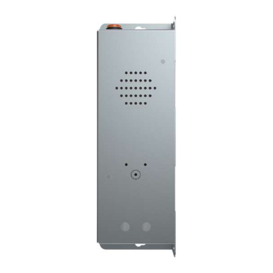
- Page 13 2N® LiftIP 2.0 User Manual TOC Design The electronics board is mounted in a metal cover (see the Fig.). The overall dimensions are 82 (W) x 186 (H) x 33 (D0) mm for the basic version and 82 (W) x 257 (H) x 33 (D) mm for the long ®...
- Page 14 The count and types of accessories may differ in different Part Nos. ® LiftIP 2.0 Installation Conditions ® • LiftIP 2.0 is not designed for outdoor applications. • The product is connected to the LAN. • The covering against mechanical damage, water, dust and other adverse effects must be provided by the installing company if necessary.
- Page 15 ® LiftIP 2.0 Position ® ® Mount 2N LiftIP 2.0 into any position as needed. The optimum position of 2N LiftIP 2.0 is ® approximately at the adult’s mouth height. 2N LiftIP 2.0 is designed for places where any touch of the operating personnel is excluded (refer to Security Precautions).
- Page 16 Make sure that there is no gap ® between the button panel and 2N LiftIP 2.0 panel or seal the gap if any properly to avoid the speaker acoustic fault and speaker – microphone acoustic feedback (see later). ...
- Page 17 2N® LiftIP 2.0 User Manual Warning • Make sure that the microphone hole is sealed against the noise that might get into the microphone through the gap between the cabin wall and the mounting panel. The microphone is supposed to receive sounds from the cabin only and not from ®...
- Page 18 ® LiftIP 2.0 Connection ® LiftIP 2.0 is connected to the LAN via a Cat-5e or higher UTP cable terminated with RJ-45 ® (LAN connector). 2N LiftIP 2.0 can be fed via PoE or from an external power supply (10–30 V DC, ®...
- Page 19 2N® LiftIP 2.0 User Manual Caution • Fit the Ethernet cable to the motherboard using a cable tie to prevent mechanical stress of the connector. ALARM 1/2 Connection – Contact Control Accident Risk • Remember that the button must be safe – the button contacts may never be connected to any other circuits.
- Page 20 Any indicators can be used in this connection mode (illuminated pictograms, e.g.). The indicator ® brightness intensity is ensured by the use of an external power supply. 2N LiftIP 2.0 includes just switches; connect a circuit to limit the current if necessary if LEDs are used. ...
- Page 21 2N® LiftIP 2.0 User Manual Cable connected LEDs Used where no illuminated pictograms are available. Such LEDs are part of the device cable version accessories. They are LEDs with the diameter of 5 mm and very high luminosity. Requirements •...
- Page 22 ® • The 2N LiftIP 2.0 is set to contact control from the factory. Both the jumpers are mounted on the configuration jumper. • CANCEL can be set to N/C contact too. If the case is a N/C contact, invert the CANCEL input function in the device web configuration, refer to 4.4.2 Input...
- Page 23 2N® LiftIP 2.0 User Manual Requirements • We recommend that the induction loop is located behind a non-magnetic cover to avoid the induction loop field radiation worsening. • Make sure that the induction loop is marked with an appropriate pictogram (ear) and its position meets the standard requirements.
- Page 24 2N® LiftIP 2.0 User Manual 2.5 Description of Terminals, Jumpers, Connectors and LEDs Description of terminals and connectors Short press (VOL−) − turn down the speaker volume Button VOL−, Long press (RESET) – restart the device in approx. 10 s RESET, Very long press (CONFIG) −...
- Page 25 2N® LiftIP 2.0 User Manual Description of terminals and connectors ETHERNET + RJ-45 (PoE according to802.3af) LAN connector DC IN 10–30 V External 10–30 V DC terminal power supply (unless PoE is available) Indicator 12–24 V DC / 2× 200 mA externally supplied indicators; keep the wiring connecting diagram.
- Page 26 2N® LiftIP 2.0 User Manual Description of terminals and connectors Contact N/O contact Use the configuration jumpers control (default) for setting. N/O contact: both the jumpers are mounted. N/C contact N/C contact: both the jumpers are mounted and input polarity is inverted in the software configuration in S.
- Page 27 2N® LiftIP 2.0 User Manual Description of terminals and connectors Contact N/O contact Use the configuration jumpers control (default) for setting. N/O contact: both the jumpers are mounted. N/C contact N/C contact: both the jumpers are mounted and input polarity is inverted in the software configuration in Subs.
- Page 28 Relax Signals the device relax state. Note ® • The LEDs are located on the 2N LiftIP 2.0 audio unit front side. • External LEDs can be connected too (Establishing connection, Connection established). 2.6 Button Functions The buttons located in the left-hand upper part of the main unit board are used for setting basic parameters and controlling the device without access to the device web interface.
- Page 29 2N® LiftIP 2.0 User Manual Volume Control Press the VOL−/VOL+ button shortly to turn down/up the speaker volume by one level. The master volume low/high limit is confirmed by an acoustic signal. ALARM 1/2 Default Setting Press the AUTODETECT button for approx. 10 s to detect the ALARM 1/2 input control type. The detected values are automatically written into the software configuration.
- Page 30 2N® LiftIP 2.0 User Manual Note • The time interval between the RESET press and the first light and acoustic signals is approx. 30 s. Static IP address setting To switch on the static IP address mode (DHCP OFF), follow the instructions below: •...
- Page 31 2N® LiftIP 2.0 User Manual Dynamic IP address setting Follow the instructions below to switch on the Static IP address mode (DCHP ON): • Press and hold the RESET button. • Wait until the red and green LEDs go on simultaneously on the device and the acoustic signal can be heard (approx.
- Page 32 2N® LiftIP 2.0 User Manual • Wait until the red LED goes off and the acoustic signal can be heard (approx. for another 3 s). • Wait until the green LED goes off and the red LED goes on again and...
- Page 33 Description ® ® Voice Alarm Station extends 2N LiftIP 2.0 to include audio units on the cabin roof and under the cabin. It is equipped with its own microphone, speaker and alarm button. A switch ® helps interconnect 2N LiftIP 2.0 with one or two audio units. ...
- Page 34 Caution • The audio unit does not include a connection establishing LED indicator. The call ® setup and confirmation are indicated by a LED on the 2N LiftIP 2.0 audio unit. Mounting ® Mount the interconnection cable connector on the 2N LiftIP 2.0 extender jumper.
- Page 35 2N® LiftIP 2.0 User Manual Warning ® • Disconnect 2N LiftIP 2.0 from the power supply (10–30 V DC or PoE) while ® connecting 2N Voice Alarm Station. • Make sure that all the pins are mounted correctly into the pin connector.
- Page 36 (SPK and MIC). Pull the enclosed cables through the holes. Caution ® • If you use the 2N LiftIP 2.0 cable version, connect the microphone on the cable to the MIC connector, otherwise the connectors remains unmounted. 36 / 119...
- Page 37 The 2N LiftIP 2.0 Relay extender extends 2N LiftIP 2.0 to include one additional output. The relay output type makes it posible to switch both voltage polarities. The blocking output opens/ closes according to the setting if it is impossible to set up an alarm call (no Proxy registration, no ®...
- Page 38 2N® LiftIP 2.0 User Manual Wiring Diagram ® The 2N LiftIP 2.0 Relay extender is connected into the RELAY connector (see 2.5 Description of LEDs, Terminals, Jumpers and Connectors). ® ® Interconnect 2N LiftIP 2.0 and 2N LiftIP 2.0 Relay extender using a cable.
- Page 39 LiftIP 2.0 Relay extender. • To protect the circuits against short circuit with other conductive objects, put ® LiftIP 2.0 Relay extender into an insulation tube and secure it with cable ties before installation! • Keep the proper connection (yellow wire).
- Page 40 2N® LiftIP 2.0 User Manual Output Type galvanically isolated, enables both voltage polarities to be switched Diagram Example: Use the COM and NO contacts to make the relay connect the circuit after voltage is carried to the coil. 40 / 119...
- Page 41 ® Network Scanner Description The application is used for retrieving the IP addresses of all the 2N IP devices in the LAN. application is freely downloadable from the 2N web (www.2n.com). Make sure that Microsoft .NET Framework 2.0 is installed for successful app installation.
- Page 42 If the default password has been changed (upon the web interface login), use the current password. If not, the default password is 2n. If the found device is grey highlighted, its IP address cannot be configured using this application. In that case, click Refresh to find the device again and check whether multicast is enabled in your network.
- Page 43 2N® LiftIP 2.0 User Manual ® Change of Device IP Address in 2N Network Scanner 43 / 119...
- Page 44 Typically, configuration takes place via a web interface of the device. Alternatively, configuration can take place via My2N. ® LiftIP 2.0 is configured using a PC equipped with any Internet browser: • Launch your Internet browser (Chrome, Firefox, Internet Explorer, etc.).
- Page 45 Some tiles also display the state of selected services. Configuration Menu ® The 2N LiftIP 2.0 configuration is divided into 5 main menus – State, Directory, Services, Hardware and System – and their submenus, refer to the list below. State •...
- Page 46 2N® LiftIP 2.0 User Manual • Maintenance – set the backup and configuration reset, firmware update. • 4.1 State • 4.2 Directory • 4.3 Services • 4.4 Hardware • 4.5 System • 4.6 Used Ports 4.1 State Here is what you can find in this section: •...
- Page 47 2N® LiftIP 2.0 User Manual • Lift ID – display the lift / lift communicator ID to be sent or read in calls. The identification number has to consist of 16 digits at most. • Last Successful Checking Call – display the last successful checking call time.
- Page 48 2N® LiftIP 2.0 User Manual • Factory Certificate Installed – specification of the user certificate and private key used for verification of the device authorization to communicate with the third party server. • Locate Device – optical and acoustical device signaling. Optical signaling includes pictogram indicators, acoustic signaling is based on a connected speaker.
- Page 49 2N® LiftIP 2.0 User Manual 4.1.3 Services The Services folder provides information on the network interface state and selected services. 4.1.4 Call Log The Call Log folder shows a list of all accomplished calls. Every call includes information on its time and date, duration and status (incoming, outgoing and missed).
- Page 50 2N® LiftIP 2.0 User Manual The search field provides fulltext search in call names. The checkbox helps you select all the records to be bulk deleted. Click the button to delete a selected call record individually. The list includes the last 20 records.
- Page 51 2N® LiftIP 2.0 User Manual • – the button helps you export all the logged events into a CSV file. Event Meaning AudioLoopTest Audio test result. CallSessionStateChanged Provides information on the current call phase (creation, connecting, ringing, connected, terminated). CallStateChanged Indicates a call state change (ringing, connected, terminated) including call direction (incoming, outgoing) and counterparty identification.
- Page 52 2N® LiftIP 2.0 User Manual Event Meaning InputChanged Logic input change. KeyPressed Key pressing event. KeyReleased Key releasing event. LoginBlocked Entering of 3 wrong logins to the device web. Contains information on the login IP address. OutputChanged Logic output change.
- Page 53 Enter sip:[user_id@]domain[:port] for the so-called direct SIP calling, e.g.: sip:200@192.168.22.15 or sip:name@yourcompany. Enter device:device ID for local calls to 2N IP devices and answering units. Set the device name for the relevant devices. Enter RAVA:device_name to make Crestron calls. If you enter /1 or /2 after the phone number, SIP account 1 or 2, respectively, will be used for outgoing calls explicitly.
- Page 54 2N® LiftIP 2.0 User Manual • By Answer • Protocol Autodetection • CPC Antenna • CPC Antenna Ext • CPC KONE • P100 54 / 119...
- Page 55 The CPC protocol uses up to 16 digits for lift identification, P100 uses only 8 digits. 4.3.2 Phone ® The Phone service is the basic function of 2N LiftIP 2.0 allowing you to establish connections with other IP network terminals. The device supports the extended SIP and is compatible with major SIP PBX and terminal equipment manufacturers. ...
- Page 56 The stream parameters (port numbers, protocols and codecs) are defined and negotiated via the SDP (Session Description Protocol). ® LiftIP 2.0 supports three SIP signaling types: • Using the UDP, which is the most common unsecured way of signaling,...
- Page 57 SIP 1 and SIP 2 ® LiftIP 2.0 enables you to configure two independent SIP accounts (SIP1 and SIP2 folders). Thus, e.g., the device can be registered with two different SIP PBXs under two phone numbers at the same time. Both the SIP accounts process incoming calls equivalently. Outgoing calls are primarily processed by account 1.
- Page 58 2N® LiftIP 2.0 User Manual • Use Authentication ID – enable the use of an alternative ID for device authentication. If disabled, the Phone number defined above is used for authentication. • Authentication ID – set an alternative user ID for device authentication.
- Page 59 2N® LiftIP 2.0 User Manual • Registration Enable – enable registration with the set SIP Registrar. • Registrar Address – set the SIP Registrar IP address or domain name. • Registrar Port – set the SIP Registrar port. The device uses the default port according to the transport layer (5060 or 5061) or the port obtained from the DNS in case the parameter is empty or set to 0.
- Page 60 2N® LiftIP 2.0 User Manual • SIP Transport Protocol – set the SIP communication protocol: UDP (default), TCP or TLS. • Lowest Allowed TLS Version – set the lowest TLS version to be accepted for device connection. • Verify Server Certificate – verify the SIP server certificate against the CA certificates uploaded to the device.
- Page 61 2N® LiftIP 2.0 User Manual • IP Address Filter Enabled – enable blocking of SIP packets receiving from addresses other than SIP Proxy and SIP Registrar. The primary purpose of the function is to enhance communication security and eliminate unauthorized phone calls.
- Page 62 2N® LiftIP 2.0 User Manual Send any DTMF character into the call (e.g. press # on your IP phone) to extend the call. If the call time limit is set to 0 and SRTP is not used, the call is not time limited.
- Page 63 2N® LiftIP 2.0 User Manual Sending DTMF helps you set the method of sending DTMF characters from the device. Check the opponent’s DTMF receiving options and settings to make the function work properly. • In-Band (Audio) – enable the classic method of sending DTMF in the audio band using standardized dual tones.
- Page 64 2N® LiftIP 2.0 User Manual Video The chart helps you enable/disable the video codec H.264 offered for call setups and set its priority. • QoS DSCP Value – set the video RTP packet priority in the network. The set value is sent in the TOS (Type of Service) field in the IP packet header.
- Page 65 2N® LiftIP 2.0 User Manual Sound Assignment • Language 1, 2, 3 – select a language for the device sound messages. If a file is mapped for the given event for which a translation is available, the message is played in the selected language.
- Page 66 2N® LiftIP 2.0 User Manual • Establishing Connection – connection establishing announcement. • Alarm Call – alarm call announcement. • Checking Call – checking call announcement. • Call Extension – call termination and possible extension announcement. • Disconnection – call termination announcement.
- Page 67 2N® LiftIP 2.0 User Manual You can record a sound file using your PC microphone. Press the button to start the record. Press the button to stop . Press the button to play the record Press Upload to upload the sound into the device. ...
- Page 68 2N® LiftIP 2.0 User Manual Note • The sound recording function is not available on browsers that fail to support the WebRTC standard. 4.3.4 Rescue Mode The rescue mode is activated after the alarm call is completed. Set the rescue ending method too while enabling the rescue mode.
- Page 69 2N® LiftIP 2.0 User Manual 4.3.5 Alarm Call ® You can store up to 4 phone numbers for alarm calls and the repetition period. 2N LiftIP 2.0 makes successive calls to the stored numbers, the repetition period is terminated automatically after a call is confirmed.
- Page 70 2N® LiftIP 2.0 User Manual • 1–4 – select the user to which the connection will be directed. • Repetition Count – set the count of calling cycles if a call is not confirmed. Caution • If the call is rejected by the called user, the user will be skipped in the next calling cycle. ...
- Page 71 2N® LiftIP 2.0 User Manual Alarm Call 2 • 1–2 – select the user to which the connection will be directed. • Repetition Count – set the count of calling cycles if a call is not confirmed. • Test ALARM2 Call –...
- Page 72 2N® LiftIP 2.0 User Manual • Period – the checking calls are repeated once in the defined count of days. The first checking call is made at a randomly selected time during the first 24 hours after the device startup.
- Page 73 2N® LiftIP 2.0 User Manual 4.3.7 Notifications Notifications is used for automatic setup of an operational call if any of the following events happens. • Rescue End – set whether or not the device shall make an operational call at the end of the rescue mode.
- Page 74 PC. The HTTPS protocol is used for the browser - device communication. Enter the login user name and password first. The default login user name and password are Admin and 2n. We recommend that you change the default password as soon as possible. 74 / 119...
- Page 75 2N® LiftIP 2.0 User Manual • Device Name – set the device name to be displayed in the right-hand upper corner of the web interface, in the login window and in other applications if necessary (Network Scanner, etc.) • Web Interface Language – set the default language after the administration web server login.
- Page 76 4.3.9 Audio Test ® LiftIP 2.0 allows you to perform a periodical check of the integrated speaker and microphone. For the test purpose, the integrated speaker generates one or more short beeps. The integrated microphone receives the generated tone and the test is successful if the tone is detected correctly.
- Page 77 2N® LiftIP 2.0 User Manual Note • If a call is active during the audio test start, the audio test is postponed until the call is completed. The audio test will be performed the moment the call is completed.
- Page 78 2N® LiftIP 2.0 User Manual • Test Status – display the current test status. • Last Test Time – display the time of the last-performed test. • Last Test Result – display the result of the last-performed test. 78 / 119...
- Page 79 2N® LiftIP 2.0 User Manual 4.4 Hardware Here is what you can find in this section: • 4.4.1 Audio • 4.4.2 Input Inversion • 4.4.3 External Camera 4.4.1 Audio You can set the call and signaling volumes for various device states in this part of configuration.
- Page 80 2N® LiftIP 2.0 User Manual • Ringtone Volume – set the incoming call ringtone volume. • Call-Progress Tone Volume – set the dialtone, ringtone and busy tone volume levels. In case the call progress tones are automatically generated by the PBX, this setting will not be applied.
- Page 81 Inverted CANCEL input – the inverted input is active when the contact is open or voltage is connected. 4.4.3 External Camera ® LiftIP 2.0 enables video to be transmitted during an alarm call from an external camera located in the lift cabin. 81 / 119...
- Page 82 . The parameters are specific for the selected IP camera model. If you use another 2N IP device as an external camera, use the following address: rtsp://ip_address/mjpeg_stream. • Username – enter the username for the external IP camera connection authentication.
- Page 83 4.5.1 Network ® LiftIP 2.0 is connected to the LAN and has to be assigned a valid IP address or obtain the IP address from the LAN DCHP server to work properly. Configure the IP address and DHCP in the Network folder.
- Page 84 2N® LiftIP 2.0 User Manual • Static IP Address – static IP address of the device. The address is used together with the below mentioned parameters if the Use DHCP Server parameter is disabled. • Network Mask – network mask setting.
- Page 85 2N® LiftIP 2.0 User Manual • Required Port Mode – set the preferred network interface port mode: Autonegotiation or Half Duplex – 10 Mbps. The lower bit rate of 10 Mbps may be necessary if the used network infrastructure (cabling) is not reliable for the 100 Mbps traffic. ...
- Page 86 2N® LiftIP 2.0 User Manual Press to start remote capturing. It is necessary to specify the time (s) during which the incoming and outgoing packets shall be captured. When the time passes, the packet capture file will automatically be downloaded into the user PC. Press to stop capturing.
- Page 87 4.5.2 Date and Time ® LiftIP 2.0 is equipped with a real time clock to back up the device for even a few days in the case of power outage. Press the Synchronize with browser button to synchronize the device time with your current PC time value.
- Page 88 4.5.3 Certificates ® Some 2N LiftIP 2.0 network services use the secure TLS protocol for communication with the other LAN devices. This protocol prevents third parties from eavesdropping or modifying call contents. TLS communication is based on one/two-sided authentication, which requires certificates and private keys.
- Page 89 2N® LiftIP 2.0 User Manual ® LiftIP 2.0 allows you to upload sets of CA certificates, which are used for identity verification of the communicating device, and upload user certificates and private keys used for communication encryption. Each certificate requiring service can be assigned one certificate set, refer to the Web Server subsection.
- Page 90 2N® LiftIP 2.0 User Manual Click to upload a certificate saved on your PC into the device. Select the certificate (or private key) file in the dialog box and click Upload. Press to remove the certificate. Press to show certificate information.
- Page 91 2N® LiftIP 2.0 User Manual 4.5.4 Auto Provisioning ® LiftIP 2.0 helps you update firmware and configuration manually or automatically from a storage on a TFTP/HTTP server selected by you according to predefined rules. ® The TFTP and HTTP server addresses can be configured manually. 2N LiftIP 2.0 supports...
- Page 92 2N® LiftIP 2.0 User Manual The folder provides information on the device connection to My2N. • My2N ID – unique identifier of the company created via the My2N portal. Firmware The Firmware folder helps you set automatic firmware download from a server defined by you.
- Page 93 2N® LiftIP 2.0 User Manual • Firmware Update Enabled – enable automatic firmware download from the TFTP/HTTP server. • Address Retrieval Mode – select whether the TFTP/HTTP server address shall be entered manually or a value retrieved automatically from the DHCP server using Option 66 (or 150) shall be used.
- Page 94 2N® LiftIP 2.0 User Manual Info • The device contains Factory Cert, a signed certificate used for British Telecom integration, for example. • At Boot Time – enable check and, if possible, update execution upon every device start. •...
- Page 95 2N® LiftIP 2.0 User Manual Result Description Invalid file path The provisioning file location is invalid. DHCP option 66 The server address loading via DHCP Option 66 or 150 has failed. failed Invalid domain The server domain name is invalid due to wrong configuration or name unavailability of the DNS server.
- Page 96 2N® LiftIP 2.0 User Manual • Address Retrieval Mode – select whether the TFTP/HTTP server address shall be entered manually or a value shall be retrieved automatically from the DHCP server using Option • Server Address – enter the TFTP (tftp://ip_address), HTTP (http://ip_address) or HTTPS (https://ip_address) server address manually.
- Page 97 2N® LiftIP 2.0 User Manual • At Boot Time – enable check and, if possible, update execution upon every device start. • Update Period – set the update period. Set an automatic update to take place hourly/ daily/weekly/monthly, or set the period manually.
- Page 98 The test result is displayed in the Connection status. 4.5.5 Syslog ® LiftIP 2.0 allows you to send system messages to the Syslog server including relevant information on the device states and processes for recording, analysis and audit. It is unnecessary to configure this service for common operations.
- Page 99 2N® LiftIP 2.0 User Manual List of Parameters • Send Syslog Messages – enable sending of syslog messages to the Syslog server. Make sure that the server address is valid. • Server Address – set the IP/MAC address of the server on which the Syslog application is running.
- Page 100 4.5.6 Maintenance ® This menu helps you maintain the 2N LiftIP 2.0 configuration and firmware. You can back up and restore all the parameters, upgrade firmware and/or factory reset the device. • Restore Configuration – restore configuration from a previous backup. Press the button to display a dialog box to select and upload the configuration file to the device.
- Page 101 After the restart, it becomes fully operational with a new firmware version. The whole upgrading process takes less than one minute. Download the current firmware version for your device from www.2n.com. FW upgrade does not affect configuration. The device checks the firmware file and prevents you from uploading an incorrect or corrupt file.
- Page 102 Send Anonymous Statistics Data – enable sending of anonymous statistic data on device usage to the manufacturer. No such delicate information as passwords, access codes or phone numbers are included. This information helps 2N TELEKOMUNIKACE a.s. improve the software quality, reliability and performance. You can participate in this voluntarily and cancel your statistic data deliveries any time.
- Page 103 2N® LiftIP 2.0 User Manual 4.6 Used Ports Service Port Protocol Direction Configurable Settings 9 000 DHCP In/Out TCP/UDP In/Out 103 / 119...
- Page 104 ® to check the 2N LiftIP 2.0 function. The operation is the same as with an outgoing call. The difference is that a different announcement is played, e.g. “This is a checking call”, and a different set of phone numbers is used (refer to 4.3.6 Checking...
- Page 105 As the only purpose of 2N LiftIP 2.0 is to call for help when a person gets trapped in a lift, no call is necessary if the cabin door is open. If the lift is equipped with a door contact, connect the ®...
- Page 106 DTMF Control during Call You can use tone dialing (if Automatic dialing with confirmation is enabled) during a call to ® control 2N LiftIP 2.0 as shown below. Commands 1 through 4 are arranged conveniently for typical use. DTMF character Function description ®...
- Page 107 Up to 4 phone numbers and a repetition count can be stored for calls to the control center. ® ® LiftIP 2.0 then tries to call the set numbers one by one. 2N LiftIP 2.0 uses tone dialing (DTMF) as the most reliable confirmation method. The control center has to press the button on its phone (in the tone dialing mode) during manual call answering.
- Page 108 2N® LiftIP 2.0 User Manual Situation ® LiftIP 2.0 Confirms the connection (“Connection DTMF character confirmed"), mutes the announcement played and the call takes the maximum preset time (Maximum call time). These digits are interpreted as control characters. Confirmation by Off-Hook VOIP ...
- Page 109 ® Call 2N LiftIP 2.0 and enter the rescue end confirming password (*password*) during the call to end the rescue process. Or, press ALARM2 in the lift cabin. The audio unit announces "Rescue process has been ended" when the rescue process has been completed.
- Page 110 Set the operation via the web interface, refer to 4.3.7 Notifications. 5.6 CPC and P100 Protocols The CPC protocol supports 3 options: KONE, Antenna and Antenna 2N Ext. The data message consists of: Command – Call type – DATA – ID CPC KONE...
- Page 111 2N® LiftIP 2.0 User Manual CPC Antenna Call type Command Call type Data ID Alarm Lift ID Alarm 2 Lift ID Checking Call Lift ID Rescue process ended Lift ID Button Error Lift ID Button Fixed Lift ID Audio Error...
- Page 112 The Button fixed/Audio fixed information is only transmitted via the 2N Ext protocol. • If the 2N Ext mode is not set, the operational call cannot be established. • The CPC protocol uses up to 16 digits for lift identification, P100 uses only 8 digits.
- Page 113 2N® LiftIP 2.0 User Manual Example This is only a part of the data message. It does not contain the beginning, checksum and end. • 287654321500 – Rescue process ended, identification number 87654321. 113 / 119...
- Page 114 2N® LiftIP 2.0 User Manual 6. Technical Parameters Electric Parameters • Supply voltage: 10–30 V DC (keep polarity) or 48 V PoE 802.3af • Power consumption: up to 2 W ALARM and CANCEL voltage range • Inputs: 5–48 V DC (keep polarity) Audio Parameters •...
- Page 115 2N® LiftIP 2.0 User Manual 7. Supplementary Information • 7.1 General Instructions and Cautions • 7.2 Directives, Laws and Regulations • 7.3 Terms and Symbols 7.1 General Instructions and Cautions Please read this User Manual carefully before using the product. Follow all instructions and recommendations included herein.
- Page 116 Do not throw battery packs into fire. Battery packs may not be taken into parts or short-circuited either. 7.2 Directives, Laws and Regulations ® LiftIP 2.0 conforms to the following directives and regulations: • 2014/35/EU for electrical equipment designed for use within certain voltage limits •...
- Page 117 2N® LiftIP 2.0 User Manual energy and, if not installed and used in accordance with the instructions, may cause harmful interference to radio communications. However, there is no guarantee that interference will not occur in a particular installation. If this...
- Page 118 2N® LiftIP 2.0 User Manual 7.3 Terms and Symbols The following symbols and pictograms are used in the manual: Safety • Always abide by this information to prevent persons from injury. Warning • Always abide by this information to prevent damage to the device.
- Page 119 Uživatelský manuál 2N® LiftIP 2.0 119 / 119...
Need help?
Do you have a question about the LiftIP 2.0 and is the answer not in the manual?
Questions and answers