Table of Contents
Advertisement
Quick Links
Advertisement
Table of Contents

Subscribe to Our Youtube Channel
Summary of Contents for COMAC CAL FLOW 32
- Page 1 FLOW 32 Ver. 4.0 Installation and technical conditions Date of issue 18/06/2019...
-
Page 2: Table Of Contents
Display ............................. 16 Functional checks ........................17 Failures and their symptoms during measurement ............... 17 Order code ..........................17 Servicing ..........................18 Returning the meter to COMAC CAL s.r.o................18 FLOW 32 manual Page 2 (total 18) COMAC CAL s.r.o. -
Page 3: Description Of The Device
In case of returning the meters for inspection or repair to the COMAC CAL s.r.o. factory, enclose please the completed form, see the last page of this manual. Without having one, we will not be able to handle your requirement for modification or possibly repair your meter correctly and promptly. -
Page 4: Installation In Pipeline
FLOW 32 manual Page 4 (total 18) -
Page 5: Installation Examples
5d before the flow sensor and 3d after the flow sensor where d is the inside diameter of the meter in millimetres. The same principles apply before and after the flow sensor in case of bi-directional flow measurement. FLOW 32 manual Page 5 (total 18) COMAC CAL s.r.o. -
Page 6: Actual Installation In Pipeline
U-profile in such a way that constant immersion of the electrodes is ensured. FLOW 32 manual Page 6 (total 18) COMAC CAL s.r.o. - Page 7 For the meter, it is necessary to respect the temperature of medium up to 70 °C. In case of exceeding this temperature, the correct functionality of the electronic evaluation unit is not guaranteed, or there is a risk of its destruction. FLOW 32 manual Page 7 (total 18) COMAC CAL s.r.o.
-
Page 8: Installation Check
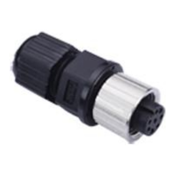
PIN 4 – Service communication (Rxd) PIN 5 – OUT3 failure (collector – positive potential) PIN 6 - Analog output 4÷20mA + PIN 7 - GND PIN 8 - +Vdd (24VDC±15%) FLOW 32 manual Page 8 (total 18) COMAC CAL s.r.o. -
Page 9: Impulse Output Out1/Out2
- Flow switch functions - Shift phase The transistor rating should be selected so that its limit parameters cannot be exceeded (200mA/100mW max.). Wiring example: Maximum frequency of the impulse output is 16kHz. FLOW 32 manual Page 9 (total 18) COMAC CAL s.r.o. -
Page 10: Status Output Out3
4-20mA in flow direction shifted flow monitoring (in flow direction impulses in flow direction 4-20mA in flow direction only) FLOW 32 manual Page 10 (total 18) COMAC CAL s.r.o. -
Page 11: Wiring Check
Meter is temporarily beyond parameters <4mA Supply voltage error Flow direction: The arrow indicates the direction liquid flow inside the sensor and thus the correct orientation of the meter's sensor for installation in piping. FLOW 32 manual Page 11 (total 18) COMAC CAL s.r.o. - Page 12 In case of a high temperature of the medium, the flow meter itself can be heated up so you must be careful and avoid contacting the device. FLOW 32 manual Page 12 (total 18) COMAC CAL s.r.o.
-
Page 13: Technical Data
70ms (current loop) Process connection threaded (EN ISO 228-1) Sampling: 900 samples per second (standard) 55°C Max. ambient temperature Ambient humidity: max. 90% Pressure PN25 Pressure loss negligible Meter IP code IP65 FLOW 32 manual Page 13 (total 18) COMAC CAL s.r.o. -
Page 14: Factory Settings
4 – 20mA (in Qmin/Qmax 1/100 range) Diameter Impulse output nominal Vout[imp/l] Vout - pulse width [ms] Q[l/h] for 4mA Q[l/h] for 20mA 1200 2200 3 400 7 600 14 200 FLOW 32 manual Page 14 (total 18) COMAC CAL s.r.o. -
Page 15: Basic Detector Sizes
Basic detector sizes Threaded design Diameter Compact flow Threaded nominal meter weight connection [mm] (kg) ½“ 16.5 ½“ 16.5 ½“ 16.5 ½“ 16.5 ½“ 16.5 ¾“ 16.5 FLOW 32 manual Page 15 (total 18) COMAC CAL s.r.o. -
Page 16: Display
E-button is pressed and held for approx. 4 seconds). After this period is over, it is only possible to view the current settings, the modification of parameters is blocked). Button ↑ changes parameters and button E confirm values. FLOW 32 manual Page 16 (total 18) COMAC CAL s.r.o. -
Page 17: Functional Checks
Unstable indication and outputs may occur upon: high proportion of solids latent non-homogeneities dislocation of mixing ongoing chemical reactions within the measured substance use of diaphragm pumps or piston-type pumps Order code FLOW 32 manual Page 17 (total 18) COMAC CAL s.r.o. -
Page 18: Servicing
Please attach full description of the fault. COMAC CAL s.r.o. will not be able to process your request promptly and correctly without this form.


Need help?
Do you have a question about the FLOW 32 and is the answer not in the manual?
Questions and answers