
Related Manuals for COMAC CAL FLOW 45


Summary of Contents for COMAC CAL FLOW 45
- Page 1 FLOW 45 Installation and technical conditions Date of issue 11/05/2017 Manual FLOW 45 Page 1 (total 28) COMAC CAL s.r.o.
-
Page 2: Table Of Contents
Reduction in DN pipe ........................26 Faults and their symptoms during measurement ................27 Flow sensor cleaning .......................... 27 Servicing .............................. 27 Form for shipment of the meter back to COMAC CAL s.r.o............28 Manual FLOW 45 Page 2 (total 28) COMAC CAL s.r.o. -
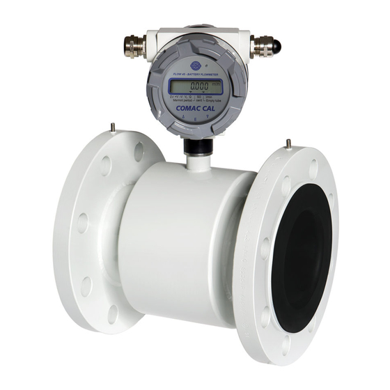
Page 3: Description Of Device
This is picked up by two electrodes in direct contact with the measured medium and evaluated in the electronic unit. The FLOW 45 type of induction meters are suitable exclusively for measurement of volumetric flow of electrically conductive liquid substances with a minimum conductivity of 50 S/cm (at a lower conductivity, upon agreement with the manufacturer). -
Page 4: Storage Conditions
In case of returning the meters for inspection or repair to the COMAC CAL s.r.o. factory, enclose please the completed form, see the last page of this manual. Without having one, we will not be able to handle your requirement for modification or possibly repair your meter correctly and promptly. -
Page 5: Installation In Pipeline
Manual FLOW 45 Page 5 (total 28) -
Page 6: Installation Examples
Correct location Pipeline is empty; erroneous measurement Horizontally laid pipeline Long pipeline Place the sensor in a slightly Install controls and shut-off ascending pipeline valves always after the sensor Manual FLOW 45 Page 6 (total 28) COMAC CAL s.r.o. -
Page 7: Actual Installation In Pipeline
The difference of L and L distances of the sealing surfaces of the flanges before the flow sensor is installed must not be greater than 0.5 mm. Manual FLOW 45 Page 7 (total 28) COMAC CAL s.r.o. - Page 8 The measurement accuracy is maintained in this way. Once the electrode is covered with the liquid again, the error message disappears and the flow meter starts taking measurement again. Manual FLOW 45 Page 8 (total 28) COMAC CAL s.r.o.
- Page 9 If the bolts are tightened too much during the installation of pipework components, deformation of the sealing surface may occur. In consequence, the torque values indicated in the table are used as a guidance for tightening the screws and bolts. Manual FLOW 45 Page 9 (total 28) COMAC CAL s.r.o.
- Page 10 Table. For the second time, to 80% and for the third time, to 100% of the maximum torque. We recommend checking the screws/bolts for tightening some 24 hours after installation of the meter. Manual FLOW 45 Page 10 (total 28) COMAC CAL s.r.o.
- Page 11 In such cases, it is necessary to use the earthing rings for potential equalization. This holds true for two-phase or two- Manual FLOW 45 Page 11 (total 28)
- Page 12 For short pipelines, it is necessary to use flexible seals, for long pipelines, use flexible pipe elements (e.g. bends). Manual FLOW 45 Page 12 (total 28) COMAC CAL s.r.o.
-
Page 13: Installation Check
The special cable for connection of the detached meter design must not be extended or cut short. In case of infringement of these requirements, measurement failures and significant inaccuracies may occur once the meters are connected. Manual FLOW 45 Page 13 (total 28) COMAC CAL s.r.o. -
Page 14: Installation Of The Meter's Detached Evaluation Unit
Power battery pack FLOW 45 is equipped with a battery power pack. When the voltage drops below the set limit, LOWBAT will be displayed on the display. The display of this sign indicates that a battery replacement request. -
Page 15: Meter Wiring
2 Txd (original Comaccal GSM or GPRS) 3 -12V (extrnal powering) 4 Rxd (original Comaccal GSM or GPRS) Standard connection of cable on connector M12, 4pin opposite part of sensor: Manual FLOW 45 Page 15 (total 28) COMAC CAL s.r.o. -
Page 16: Wiring Check
Right after installation, piping is filled with a medium so that the electrodes cannot dry off. Flow direction: The arrow indicates the direction liquid flow inside the sensor and thus the correct orientation of the meter's sensor for installation in piping. Manual FLOW 45 Page 16 (total 28) COMAC CAL s.r.o. - Page 17 Perform electrical connection always after powering off. FLOW 45 OPERATING INSTRUCTIONS The meter is provided with two external buttons on the side of the electronics housing which are using for rolling of menu.
- Page 18 The meter setting is identifiable by the following symbols: Manual FLOW 45 Page 18 (total 28) COMAC CAL s.r.o.
- Page 19 The above file system FAT32 must also be set for the "logger" function. To activate the inserted SD card, remove the top cover and press the triple of all internal buttons located at the bottom of the flowmeter. Manual FLOW 45 Page 19 (total 28) COMAC CAL s.r.o.
-
Page 20: Technical Data
1790 g (evaluation unit in detached version) Al cast – powder coating Material 55 °C Max. ambient temperature Flow sensor protection IP65 (standard) buttons inside – a Operating Buttons outside – , E , Manual FLOW 45 Page 20 (total 28) COMAC CAL s.r.o. -
Page 21: Factory Settings
1/60 (0.2 m/s) (12 m/s) DN 15 0.13 DN 20 0.24 14.2 DN 25 0.35 DN 32 DN 40 DN 50 DN 65 DN 80 DN 100 DN 125 DN 150 Manual FLOW 45 Page 21 (total 28) COMAC CAL s.r.o. -
Page 22: Basic Sensor Sizes
Building height flow meter connection sensors [mm] of sensor of sensor sensor (kg) of comp. meter weight (kg) ½“ ¾“ 1“ 1 ¼“ 1 ½“ The Table is for PN25. Manual FLOW 45 Page 22 (total 28) COMAC CAL s.r.o. - Page 23 Outside diameter Building length Building height detached flow Building height flow meter [mm] of sensor of sensor of sensor sensor (kg) of comp. meter weight (kg) The Table is for PN25. Manual FLOW 45 Page 23 (total 28) COMAC CAL s.r.o.
- Page 24 (kg) of comp. meter weight (kg) The Table is up to DN 200 for PN25, DN250 and DN300 for PN16, DN350 and DN400 for PN10. Manual FLOW 45 Page 24 (total 28) COMAC CAL s.r.o.
- Page 25 The Table is for PN25. Diameter nominal [mm] DN 15 ÷ DN 20 DN 25 ÷ DN 40 DN 50 DN 65 DN 80 Outside dimension of CLAMP [mm] 50,5 Manual FLOW 45 Page 25 (total 28) COMAC CAL s.r.o.
-
Page 26: Nomogram For Quick Proposal Of The Measured Place
Nomogram for quick proposal of the measured place Reduction in DN pipe If the pipe’s DN is higher than that of the meter selected Manual FLOW 45 Page 26 (total 28) COMAC CAL s.r.o. -
Page 27: Faults And Their Symptoms During Measurement
When the operations described below are carried out incompetently, the claim for warranty for errors resulting from this becomes null and void !!! Turn off the power every time the evaluation unit is opened !!! Manual FLOW 45 Page 27 (total 28) COMAC CAL s.r.o. -
Page 28: Form For Shipment Of The Meter Back To Comac Cal S.r.o
Fill in the following data please and the form duly completed attach to your consignment. COMAC CAL s.r.o. will not be able to process your request promptly and correctly without this form.
Need help?
Do you have a question about the FLOW 45 and is the answer not in the manual?
Questions and answers