
Related Manuals for COMAC CAL FLOW 38


Summary of Contents for COMAC CAL FLOW 38
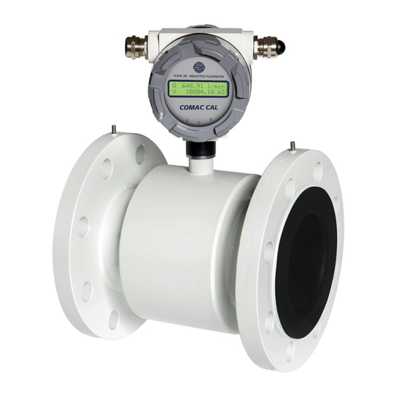
- Page 1 FLOW 38 Batch Ver.8.24 Instalation and technical manual Date of publish 07/06/2021 Technical and instalation manual FLOW 38 Batch Page 1 (of 49) COMAC CAL s.r.o.
-
Page 2: Table Of Contents
Wall mounting ..........................20 Meter wiring of batching unit ......................21 Electrical connection of the meter ....................22 Impulse output ..........................22 Buttons START, STOP ........................23 Technical and instalation manual FLOW 38 Batch Page 2 (of 49) COMAC CAL s.r.o. - Page 3 Meter status ............................25 Basic parameter settings ........................25 Safety rules for operator ........................25 Flow 38 Batch operating instructions ....................25 Functions of control (lower) buttons: ....................25 Function of setting buttons ( under display) ..................26 Basic display menu contains the following items: ................27 Meter settings via the display ......................
- Page 4 Faults and their symptoms during measurement ................48 Flow sensor cleaning .......................... 48 Servicing .............................. 48 Form for shipment of the meter back to COMAC CAL s.r.o............49 Technical and instalation manual FLOW 38 Batch Page 4 (of 49)
-
Page 5: Description Of Device
The FLOW 38 Batch type of induction meters are suitable exclusively for measurement of volumetric flow of electrically conductive liquid substances with a minimum conductivity of 20 µS/cm (at a lower conductivity, upon agreement with the manufacturer). -
Page 6: Storage Conditions
In case of returning the meters for inspection or repair to the COMAC CAL s.r.o. factory, enclose please the completed form, see the last page of this manual. Without having one, we will not be able to handle your requirement for modification or possibly repair your meter correctly and promptly. -
Page 7: Installation In Pipeline
Gas bubbles are expelled also at an abrupt pressure drop. Therefore, butterfly valves and similar elements should be located after the flow Technical and instalation manual FLOW 38 Batch Page 7 (of 49) COMAC CAL s.r.o. - Page 8 In case of any intervention into the measuring circuit must be accessed like a pipe is fulfilled of medium, and regardless of the displayed information “empty pipe test” on the display meter !!! Technical and instalation manual FLOW 38 Batch Page 8 (of 49) COMAC CAL s.r.o.
-
Page 9: Installation Examples
The same principles apply before and after the flow sensor in case of bi-directional flow measurement. Recommendations • In case of whirled up flow, extend the calming sections of pipeline or integrate a flow conditioner. Technical and instalation manual FLOW 38 Batch Page 9 (of 49) COMAC CAL s.r.o. -
Page 10: Actual Installation In Pipeline
(5×d before and 3×d in the direction of flow) whereas the liquid must run through the flow sensor in the direction indicated by the arrow on the sensor name plate. Technical and instalation manual FLOW 38 Batch Page 10 (of 49) COMAC CAL... -
Page 11: Installation Position
Measurement error caused by incorrect mounting installation 1) correct installation (flow sensor should be install in arbitrary position in vertical piping) EMPTY TEST – ON EMPTY TEST – OFF Technical and instalation manual FLOW 38 Batch Page 11 (of 49) COMAC CAL s.r.o. -
Page 12: Installation In Piping And Placement Of Measuring Electrodes In Flow Sensor
It is absolutely necessary to tighten the bolts and nuts equally by alternating sides and in the order shown in figure applying the maximum torque according to the table. Technical and instalation manual FLOW 38 Batch Page 12 (of 49) COMAC CAL... - Page 13 If the bolts are tightened too much during the installation of pipework components, deformation of the sealing surface may occur. In consequence, the torque values indicated in the table are used as a guidance for tightening the screws and bolts. Technical and instalation manual FLOW 38 Batch Page 13 (of 49) COMAC CAL s.r.o.
- Page 14 350 16 x M20 16 x M24 400 16 x M24 16 x M27 500 20 x M24 20 x M30 600 20 x M27 20 x M30 Technical and instalation manual FLOW 38 Batch Page 14 (of 49) COMAC CAL s.r.o.
- Page 15 If you do not find your size or structure in the Torque Table, it is a special or non-standard design. In such a case, contact the manufacturer for more detailed information. Technical and instalation manual FLOW 38 Batch Page 15 (of 49) COMAC CAL...
-
Page 16: Seal
However, if it is not ensured that the counter-flanges are in dicert contact with the measured media and they are conductive, the earthing rings must be used, refer hereinafter. Technical and instalation manual FLOW 38 Batch Page 16 (of 49) COMAC CAL... -
Page 17: Earthing Rings
Carry out the installation at the lowest point of the pipeline to avoid the occurrence of vacuum. Never detach and damage the rim of the PTFE lining turned up to the of flow sensor faces. Remove the covers Technical and instalation manual FLOW 38 Batch Page 17 (of 49) COMAC CAL... -
Page 18: High Temperature Pipeline And High Temperature Medium
In consequence, make sure that the serial numbers of both parts are always identical!!! Technical and instalation manual FLOW 38 Batch Page 18 (of 49) COMAC CAL s.r.o. -
Page 19: Important Information
Cover the unoccupied grommets with a piece of cable or a plastic plug (securing of tightness). Technical and instalation manual FLOW 38 Batch Page 19 (of 49) COMAC CAL... -
Page 20: Installation Of The Meter's Detached Evaluation Unit
After completion, close the unit and tighten all screw. Total depth of box is 200mm!! Technical and instalation manual FLOW 38 Batch Page 20 (of 49) COMAC CAL s.r.o. -
Page 21: Meter Wiring Of Batching Unit
Similarly, fasten the wires for supply voltage and control outputs. At this stage the device is ready to operate. The internal control board is already connected with a measuring device – this has been done inside the COMAC CAL factory. If this is not desirable, do not interfere with the wiring. Technical and instalation... -
Page 22: Electrical Connection Of The Meter
Technical and instalation manual FLOW 38 Batch Page 22 (of 49) COMAC CAL s.r.o. -
Page 23: Buttons Start, Stop
Terminals 1 and 2 are used to control the relay valve batching device. These terminals are in batching devices already connected to the control board with relay outputs. Data output The Flow 38 Batch meter can be provided with RS485 communication interface with M-Bus protocol according to EN 1434-3 or ModBus RTU. Protection degree The meters meet all the requirements for IP 65 protection degree. -
Page 24: Wiring Check
If you wish the meter to take measurement as precisely as possible right after powering up, it is a good idea to fill the flow sensor with water, one or two days before its installation, so that all of its Technical and instalation manual FLOW 38 Batch Page 24 (of 49) COMAC CAL... -
Page 25: Meter Status
Perform electrical connection always after powering off. Flow 38 Batch operating instructions The meter is provided with two external buttons on the side of the electronics housing and with three internal buttons on the bottom of the measuring electronics PCB which is accessible after unscrewing the front glazed cover. -
Page 26: Function Of Setting Buttons ( Under Display)
(long press >3sec) simultaneously and total restart of the meter (long press >8sec) short press confirmation (Enter) or modification of a value (setting) Technical and instalation manual FLOW 38 Batch Page 26 (of 49) COMAC CAL s.r.o. -
Page 27: Basic Display Menu Contains The Following Items
DISPLAY DIMMING DISPLAY BACKLIGHT SERIAL NUMBER CALIBRATION CONSTANTS EMPTY TUBE TEST FIRMWARE VERSION DEAD BAND – MEASUREMENT START SUPPRESSION* ZERO CALIBRATION* FLOW SIMULATION LANGUAGE COUNTER RESETTING* Technical and instalation manual FLOW 38 Batch Page 27 (of 49) COMAC CAL s.r.o. -
Page 28: Flow Meter Settings
*Note: Some modifications may not be valid right after saving but these will become valid after reinitialization of the meter - refer to special button functions – REBOOT Technical and instalation manual FLOW 38 Batch Page 28 (of 49) COMAC CAL... -
Page 29: Date And Time
The counter can be reset again by pressing the E button. Technical and instalation manual FLOW 38 Batch Page 29 (of 49) COMAC CAL s.r.o. -
Page 30: Out1 Setting
(on-state/off-state), furthermore, to set the output to which direction the output will respond (flow in positive direction, in opposite direction and in both directions) as well as your own switching point value. Technical and instalation manual FLOW 38 Batch Page 30 (of 49) COMAC CAL s.r.o. - Page 31 *999.9 m 99.99 m 9.999 m The status contact makes it possible to set the amount of hysteresis between Qon and Qoff states 0.1 ÷ 99.9 % Technical and instalation manual FLOW 38 Batch Page 31 (of 49) COMAC CAL s.r.o.
-
Page 32: Settings Of Dose Range
If communication was not ordered. Number of stop bits 1/2 Address 0 - 255 Transfer rate 1200Bd – 9600Bd parity: N – no parity E – even O – odd Technical and instalation manual FLOW 38 Batch Page 32 (of 49) COMAC CAL s.r.o. -
Page 33: Idle State Basic Indications On Display
Here, you can set the period during which the display backlight is turned off after the last activation of a button. Use the and buttons to select the desired settings from menu. 40 sec 20 sec 10 sec permanent Technical and instalation manual FLOW 38 Batch Page 33 (of 49) COMAC CAL s.r.o. -
Page 34: Serial Number
Activates and deactivates monitoring of measuring tube filling. If the meter was ordered without the testing electrode, the flooding test cannot be activated. Firmware version The firmware version is registered in the factory and cannot be changed by user. Technical and instalation manual FLOW 38 Batch Page 34 (of 49) COMAC CAL s.r.o. -
Page 35: Dead Band - Measurement Of Start Suppression
The customer can set the value of the simulated flow. If you want to activate or deactivate the simulation, press the E button. Number of significant digits: 6 Technical and instalation manual FLOW 38 Batch Page 35 (of 49) COMAC CAL s.r.o. -
Page 36: Language
If the medium flows through the sensor against the arrow on the sensor, select the NEGATIVE direction. If you wish to make the change, press E. Technical and instalation manual FLOW 38 Batch Page 36 (of 49) COMAC CAL s.r.o. -
Page 37: Signal Saturation Filter
). If these parameters are changed, the respective measured value will be changed as well. In consequence, we recommend resetting of the counters changed in this way after reconfiguration. Technical and instalation manual FLOW 38 Batch Page 37 (of 49) COMAC CAL... -
Page 38: User Counter With Reset Option
At the same time, the calibration constants will be set to the factory values Before activating this function, it is useful to record or make a data backup of all counters. Technical and instalation manual FLOW 38 Batch Page 38 (of 49) COMAC CAL s.r.o. -
Page 39: Technical Data
220 x 170 x 80 mm (H x W x D), Weight 2540 g (evaluation unit in detached version) Material ABS plastic Max. ambient temperature 55 °C Flow sensor protection IP65, IP67, IP68 Electronics protection IP65 Technical and instalation manual FLOW 38 Batch Page 39 (of 49) COMAC CAL s.r.o. - Page 40 1.52 % + 0.35 mm/s >= DN 15 0.5 % of M* 0.52 % + 0.8 mm/s 1.22 % + 0.35 mm/s * Of M – of the measured value Technical and instalation manual FLOW 38 Batch Page 40 (of 49) COMAC CAL s.r.o.
-
Page 41: Factory Settings
Resolution V Resolution Q nominal DN≤25 V [0.001 m3] Q [0.001 m3/h] 80≥DN>25 V [0.01 m3] Q [0.01 m3/h] DN>80 V [0.1 m3] Q [0.1 m3/h] Technical and instalation manual FLOW 38 Batch Page 41 (of 49) COMAC CAL s.r.o. - Page 42 DN 250 21.1 — 2115 DN 300 — 3050 DN 350 — 4150 DN 400 — 5426 DN 500 — — 8480 DN 600 — — 12200 Technical and instalation manual FLOW 38 Batch Page 42 (of 49) COMAC CAL s.r.o.
-
Page 43: Basic Sensor Sizes
[mm] of sensor of sensor sensor (kg) of sensor ½“ ½“ ½“ “ ½“ ¾“ 1“ 1 ¼“ 1 ½“ 2“ The Table is for PN25. Technical and instalation manual FLOW 38 Batch Page 43 (of 49) COMAC CAL s.r.o. -
Page 44: Sandwich (Inter-Flanged) Design
[mm] of sensor of sensor of sensor sensor (kg) 10*,15 The Table is for PN25. * Process connection is performed through DN 15 flange Technical and instalation manual FLOW 38 Batch Page 44 (of 49) COMAC CAL s.r.o. -
Page 45: Flanged Design
The Table is up to DN 200 for PN25, DN250 and DN300 for PN16, DN350 to DN600 for PN10. * Process connection is performed through DN 15 flange Technical and instalation manual FLOW 38 Batch Page 45 (of 49) COMAC CAL... -
Page 46: Food Industry Design
The Table is for PN25. DN 15…DN 20 DN 25…DN 40 DN 50 DN 65 DN 80 Diameter nominal [mm] 50,5 Outside dimension of CLAMP [mm] Technical and instalation manual FLOW 38 Batch Page 46 (of 49) COMAC CAL s.r.o. -
Page 47: Nomogram For Quick Proposal Of The Measured Place
Nomogram for quick proposal of the measured place Reduction in DN pipe If the pipe’s DN is higher than that of the meter selected Technical and instalation manual FLOW 38 Batch Page 47 (of 49) COMAC CAL s.r.o. -
Page 48: Faults And Their Symptoms During Measurement
When the operations described below are carried out incompetently, the claim for warranty for errors resulting from this becomes null and void !!! Turn off the power every time the evaluation unit is opened!!! Technical and instalation manual FLOW 38 Batch Page 48 (of 49) COMAC CAL s.r.o. -
Page 49: Form For Shipment Of The Meter Back To Comac Cal S.r.o
Form for shipment of the meter back to COMAC CAL s.r.o. The meter you have was made with the maximum precision and it has been checked many times and wet calibrated. If the meter is used in agreement with this manual, the occurrence of faults is very rare. Should they ever occur, contact our service department.
Need help?
Do you have a question about the FLOW 38 and is the answer not in the manual?
Questions and answers