
Related Manuals for COMAC CAL FLOW 38 BATCH


Summary of Contents for COMAC CAL FLOW 38 BATCH
- Page 1 FLOW 38 BATCH Ver.8.16 Installation and technical conditions Date of issue 1/2/2016 Manual FLOW 38 BATCH Page 1 (total 43) COMAC CAL s.r.o.
-
Page 2: Table Of Contents
Empty tube test ………………………………………………...…………………….. Page 27 Firmware version…………………………………………………………………….. Page 28 Dead band – measurement start suppression ………….…………………………… Page 28 Zero calibration……………………………..…………………………………...…..Page 28 Flow simulation ………………………………………………………………………. Page 28 Language……………………………….……………………………………………… Page 29 Manual FLOW 38 BATCH Page 2 (total 43) COMAC CAL s.r.o. - Page 3 Faults and their symptoms during measurement ………………….…………………… Page 40 Flow sensor cleaning ...…………………………………………………..……...………. Page 40 Servicing ……………………………………………………………………..……..……. Page 40 Order code ……………………………………………………………………..…………. Page 41 Form for shipmentof the meter back to COMAC CAL s.r.o. ……………………..……. Page 42 Manual FLOW 38 BATCH Page 3 (total 43) COMAC CAL s.r.o.
-
Page 4: Description Of Device
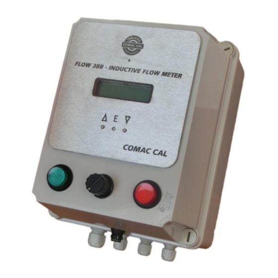
The FLOW 38 Batch type of induction meters are suitable exclusively for measurement of volumetric flow of electrically conductive liquid substances with a minimum conductivity of 20 S/cm (at a lower conductivity, upon agreement with the manufacturer). -
Page 5: Storage Conditions
In case of returning the meters for inspection or repair to the COMAC CAL s.r.o. factory, enclose please the completed form, see the last page of this manual. Without having one, we will not be able to handle your requirement for modification or possibly repair your meter correctly and promptly. -
Page 6: Installation In Pipeline
Manual FLOW 38 BATCH Page 6 (total 43) -
Page 7: Installation Examples
Recommended installation locations Downtake pipe Bubbles are accumulated in the Install an air bleed valve pipeline; erroneous measurement after the sensor Correct location Pipeline is empty; erroneous measurement Manual FLOW 38 BATCH Page 7 (total 43) COMAC CAL s.r.o. - Page 8 This will serve as an additional safety measure for detection of non-flooded tube. The responsibility for suitability and adequacy of application of induction flow meters is borne by the designer or possibly the user himself. Manual FLOW 38 BATCH Page 8 (total 43) COMAC CAL s.r.o.
-
Page 9: Actual Installation In Pipeline
The measurement accuracy is maintained in this way. Once the electrode is covered with the liquid again, the error message disappears and the flow meter starts taking measurement again. Manual FLOW 38 BATCH Page 9 (total 43) COMAC CAL s.r.o. - Page 10 If the bolts are tightened too much during the installation of pipework components, deformation of the sealing surface may occur. In consequence, the torque values indicated in the table are used as a guidance for tightening the screws and bolts. Manual FLOW 38 BATCH Page 10 (total 43) COMAC CAL s.r.o.
- Page 11 12 x M30 16 x M27 16 x M30 16 x M30 16 x M33 16 x M33 16 x M36 The flanged connection design corresponds to EN 1092-1. Manual FLOW 38 BATCH Page 11 (total 43) COMAC CAL s.r.o.
- Page 12 However, if it is not ensured that the counter-flanges are in dicert contact with the measured media and they are conductive, the earthing rings must be used, refer hereinafter. Manual FLOW 38 BATCH Page 12 (total 43) COMAC CAL s.r.o.
- Page 13 (0.3 ÷ 0.6 mm thick). After insertion of the sensor, remove the metal plates and install the screws/bolts. Manual FLOW 38 BATCH Page 13 (total 43) COMAC CAL s.r.o.
-
Page 14: Installation Check
Accuracy of execution of the pipeline calming section lengths If the sensor is protected against vibrations and mechanical damage. If the name plate (serial number) on the sensor corresponds to the one on the electronics. Manual FLOW 38 BATCH Page 14 (total 43) COMAC CAL s.r.o. -
Page 15: Wiring
Cover the unoccupied grommets with a piece of cable or a plastic plug (securing of tightness). Manual FLOW 38 BATCH Page 15 (total 43) COMAC CAL s.r.o. -
Page 16: Installation Of Meter Detached Evaluation Unit
Similarly, fasten the wires for supply voltage and control outputs. At this stage the device is ready to operate. The internal control board is already connected with a measuring device – this has been done inside the COMAC CAL factory. If this is not desirable, do not interfere with the wiring. Manual FLOW 38 BATCH Page 16 (total 43) COMAC CAL s.r.o. -
Page 17: Meter Wiring Of Sensor
Meter wiring of sensor (Standardly made in COMAC CAL factory) Evaluating unit is consists of two units: Front panel with display unit Back panel with outputs, inputs and power Manual FLOW 38 BATCH Page 17 (total 43) COMAC CAL s.r.o. -
Page 18: Impulse Output / Flowswitch Contact
Applying a signal to the GND terminal 7 or 8 you can start or stop the batch. These terminals are in batching devices already connected to the control buttons. Manual FLOW 38 BATCH Page 18 (total 43) COMAC CAL s.r.o. -
Page 19: Controling Of The Batching Valve
Terminals 1 and 2 are used to control the relay valve batching device. These terminals are in batching devices already connected to the control board with relay outputs. Data output The Flow 38 Batch meter can be provided with RS485 communication interface with M-Bus protocol according to EN 1434-3 or ModBus RTU. Protection degree The meters meet all the requirements for IP 65 protection degree. -
Page 20: Wiring Check
The meter or flow meter parameters are set by the manufacturer in accordance with the purchase order. If these values are not indicated in your purchase order, the meter will be set up using the default Manual FLOW 38 BATCH Page 20 (total 43) -
Page 21: Flow38 Operating Instructions
Perform electrical connection always after powering off. FLOW 38 BATCH OPERATING INSTRUCTIONS The meter is provided with two external buttons on the side of the electronics housing and with three internal buttons on the bottom of the measuring electronics PCB which is accessible after unscrewing the front glazed cover. - Page 22 * If the meter is delivered for billing purposes, then these parameters marked with an asterisk cannot be changed (in case of restoration of factory settings, the volumetric counter is not reset). Manual FLOW 38 BATCH Page 22 (total 43)
-
Page 23: Procedure To Set Individual Menu Items
If it is not a freely adjustable numerical item but a list of possible values, the selection is implemented by successive scrolling using the or buttons and once the desired value is displayed, you simply confirm the selection by pressing the E button. Manual FLOW 38 BATCH Page 23 (total 43) COMAC CAL s.r.o. -
Page 24: Date And Time
The counter can be reset again by pressing the E button. Manual FLOW 38 BATCH Page 24 (total 43) COMAC CAL s.r.o. -
Page 25: Impulse Output / Flowswitch
3 significant figures (999 position of rotary switch). It means for setted max. dose 1000 litres will be one step 10 litres changing by the rotary switch etc.. Manual FLOW 38 BATCH Page 25 (total 43) COMAC CAL s.r.o. -
Page 26: Communication
Total volume ∑V sum of volumes in both directions Volume (-) direction reverse flow volume -V Volume (+) direction volume in positive flow direction +V Dose setting Flow current flow Q Manual FLOW 38 BATCH Page 26 (total 43) COMAC CAL s.r.o. -
Page 27: Display Dimming
Activates and deactivates monitoring of measuring tube filling. If the meter was ordered without the testing electrode, the flooding test cannot be activated. Two levels of the empty tube test activation are available for standard conductivity ON(1) and for increased conductivity ON(2). Manual FLOW 38 BATCH Page 27 (total 43) COMAC CAL s.r.o. -
Page 28: Firmware Version
The display shows the simulated flow and current and impulse outputs of the meter correspond to this data. Such a simulated flow is not registered in the volume registry, of course. Manual FLOW 38 BATCH Page 28 (total 43) COMAC CAL s.r.o. -
Page 29: Language
If the medium flows through the sensor against the arrow on the sensor, select the NEGATIVE direction. If you wish to make the change, press E. Manual FLOW 38 BATCH Page 29 (total 43) COMAC CAL s.r.o. -
Page 30: Flow Units Displayed [Q]
This applies to calibration of the meter as well. Before activating this function, it is useful to record or make a back up of the data of all counters. Manual FLOW 38 BATCH Page 30 (total 43) COMAC CAL s.r.o. - Page 31 If you wish to apply the original factory settings, press E and use the or button to select YES from menu and then confirm by E. After confirmation of the change, the meter will have the settings it had when it was delivered by the manufacturer. Manual FLOW 38 BATCH Page 31 (total 43) COMAC CAL s.r.o.
-
Page 32: Technical Data
220 x 170 x 80 mm (H x W x D), Weight 2540 g (evaluation unit in detached version) Material ABS plastic 55 °C Max. ambient temperature Flow sensor protection IP65, IP67, IP68 Manual FLOW 38 BATCH Page 32 (total 43) COMAC CAL s.r.o. - Page 33 1.17 % + 0.35 mm/s >= DN 15 0.6 % of M* 0.52 % + 0.8 mm/s 0.97 % + 0.35 mm/s * Of M – of the measured value Manual FLOW 38 BATCH Page 33 (total 43) COMAC CAL s.r.o.
-
Page 34: Factory Settings
Vout - pulse width [ms] Diameter Resolution V Resolution Q nominal DN≤15 V [0.001 m3] Q [0.001 m3/h] 50≥DN>15 V [0.01 m3] Q [0.01 m3/h] DN>50 V [0.1 m3] Q [0.1 m3/h] Manual FLOW 38 BATCH Page 34 (total 43) COMAC CAL s.r.o. - Page 35 DN 100 DN 125 5.34 2.67 DN 150 DN 200 13.5 6.75 1350 DN 250 21.1 — 2115 DN 300 — 3050 DN 350 — 4150 DN 400 — 5426 Manual FLOW 38 BATCH Page 35 (total 43) COMAC CAL s.r.o.
-
Page 36: Basic Sensor Sizes
Compact nominal Outside diameter Building length Building height detached flow Building height flow meter [mm] of sensor of sensor of sensor sensor (kg) of comp. meter weight (kg) 10*,15 Manual FLOW 38 BATCH Page 36 (total 43) COMAC CAL s.r.o. - Page 37 10*,15 The Table is up to DN 200 for PN25, DN250 and DN300 for PN16, DN350 and DN400 for PN10. * Process connection is performed through DN 15 flange Manual FLOW 38 BATCH Page 37 (total 43) COMAC CAL s.r.o.
- Page 38 The Table is for PN25. Diameter nominal [mm] DN 15 ÷ DN 20 DN 25 ÷ DN 40 DN 50 DN 65 DN 80 Outside dimension of CLAMP [mm] 50,5 Manual FLOW 38 BATCH Page 38 (total 43) COMAC CAL s.r.o.
-
Page 39: Nomogram For Quick Proposal Of The Measured Place
Nomogram for quick proposal of the measured place Reduction in DN pipe If the pipe’s DN is higher than that of the meter selected Manual FLOW 38 BATCH Page 39 (total 43) COMAC CAL s.r.o. -
Page 40: Faults And Their Symptoms During Measurement
Turn off the power every time the evaluation unit is opened !!! All repairs within warranty and after warranty period are only conducted by the manufacturer, COMAC CAL s. r.o. Manual FLOW 38 BATCH Page 40 (total 43) COMAC CAL s.r.o. -
Page 41: Order Code
Order code Manual FLOW 38 BATCH Page 41 (total 43) COMAC CAL s.r.o. -
Page 42: Form For Shipmentof The Meter Back To Comac Cal S.r.o
Fill in the following data please and the form duly completed attach to your consignment. COMAC CAL s.r.o. will not be able to process your request promptly and correctly without this form. - Page 43 Date……………………….. Signature and stamp………………………. Manual FLOW 38 BATCH Page 43 (total 43) COMAC CAL s.r.o.
Need help?
Do you have a question about the FLOW 38 BATCH and is the answer not in the manual?
Questions and answers