Table of Contents
Advertisement
Quick Links
Advertisement
Table of Contents

Related Manuals for EMS 5001


Summary of Contents for EMS 5001
- Page 1 Portable Exhaust Gas Analyzer Operators Manual Rev.9 Model # 5001 (4 & 5 Gas) Model # 8000 (Wireless) Emissions Systems, Inc. 480 Wright Dr. Lake In The Hills, IL. 60156 Voice & Fax: 1-847-669-8044 Website: www.emsgas.com Email Address: sales@emsgas.com...
-
Page 2: Table Of Contents
Table of Contents Technical Data ................Page 3 General Information..............Page 4 LED and Button Operation Model 5001........Page 5 Rear Panel Description............Page 6 Gas Analyzer Preparation............Page 7 Gas Analyzer Operation............Page 8-9 Error Codes................Page 10 Calibration................. Page 11 Maintenance................ -
Page 3: Technical Data
Technical Data Power: 10 -16 VDC Ranges: HC: 0 - 2000 ppm (0-20,000 ppm High Range) CO: 0 - 10% CO2: 0 - 20% 0 - 25% NO: 0 - 5000 ppm ( Nitric Oxide ) * · Warm up: Less than 5 minutes ·... -
Page 4: General Information
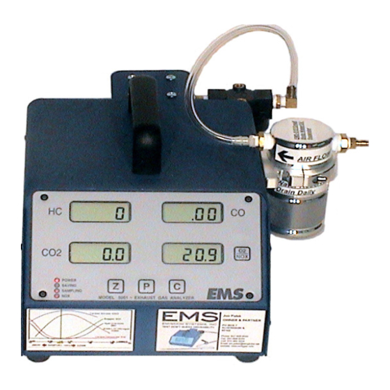
Figure 1 highlights the features and buttons available on the Model 5001 front display area. If you purchased a 4-Gas analyzer the “O2/NOX” button is inactive. The “Z”, “P” and “C”... -
Page 5: Led And Button Operation Model 5001
LED and Button Operation Model 5001 Figure 2 Figure 2 shows the LED display from the lower left corner of the gas analyzer: Power LED: This LED will illuminate when power is applied to the analyzer. Saving LED: This LED is not currently used. -
Page 6: Rear Panel Description
Rear Panel Description Figure 4 Figure 4 shows the view from the back of the analyzer. The specific details of each item are described below, starting from the upper left corner of the analyzer and working clockwise. Sample Hose Connection: The sample hose connection uses a quick disconnect coupler. -
Page 7: Gas Analyzer Preparation
Getting started is simple. Figure 5 shows the items you should have received in the shipping container. Note: This description applies to the Model 5001 analyzer with a display, see Page 13 for instructions on setting up a Model 8000 bluetooth wireless analyzer. -
Page 8: Gas Analyzer Operation
Gas Analyzer Operation Immediately after applying power, the analyzer will display 8’s (Figure 9) for a few seconds and then flash dashes (Figure 10). This starts the analyzer warm-up mode and will continue for approximately 5 to 10 minutes, depending on ambient temperature. Once the warm-up mode is complete, the analyzer will go into the gas sample mode (Figure 11) and the Sample LED will turn ON. - Page 9 Computer Connection: PC software can enhance the diagnostic benefits of the ana- lyzer. The analyzer can be connected to a PC using a 9 pin serial communications cable. EMS offers software that will display the sample gases, graph data and record information. Using the portable gas analyzer with a laptop will help diagnose problems that only occur when driving.
-
Page 10: Error Codes
“400” in the O2/NOX window indictes “CO2” out of range. When this error message is dis- played, the analyzer MUST be sent to EMS for a bench diagnosis. Please send the unit to 801 N. Harrison St., Algonquin IL. 60102, and indicate in writing what the error code is that oc-... -
Page 11: Calibration
(Figure 14). The calibration assembly can be pur- chased from EMS or your local distributor. The recommended calibration gas is Bar 97 Low and can be purchased from EMS or a local specialty gas supplier. -
Page 12: Maintenance
Check the sample hose for leaks first, check the external filter next and finally the internal hoses. Contact EMS or your local distrubutor for assistance if required. 2. The External Filter should be checked often (Figure 16). This filter catches most of the particles and impurities. - Page 13 Maintenance Internal Analyzer Maintenance: The maintenance items discussed below are located inside the analyzer. The outside cover will need to be removed to gain access. The cover is held in place with 11 screws, 5 on each side panel and one at the top behind the handle. 3.
- Page 14 Take the cap off the old filter before discarding and re-attach to the filter drain. 3) O2 Sensor; part #: EMS-5060; 12-18 month (1- 1 1/2 Year) Interval or ERROR code C WARN 5002 model.
- Page 15 Connect the sample hose to the analyzer and plug the end of the probe with the red/black plastic cap supplied by EMS. The same low flow codes will come up as described above and the low flow should hold for 30 seconds.
- Page 16 The separator will work better in colder weather, to enhance the capability of the separator in hot humid weather, EMS recommends to make a home made oil/water condensor by attaching a ICE bath. This can be done with a plastic cup filled with ice around the reservoir, or you can use a can cooler with a plastic sandwich bag around it to hold the melted water.
- Page 17 Maintenance Small Body Oil/Water Large Body Oil/Water Separator EMS-5151 Separator EMS-5150 Oil/Water Separator with Plastic Cup Ice Bath...
- Page 18 Oil/Water Separator with Can Cooler Ice Bath · Diesel Testing when Urea is used to reduce NOX (SCR) : The EMS analyzer is fully capable of diesel testing. Your HC reading will only be accurate for Hex- ane gas, so a Smoke/Opacity meter would be required to check PM. All other gases will be accurate including NOX.
- Page 19 EMS-5257 USB to Serial Adapter 13" EMS-5258 DB9 Serial Cable 6 ft Long EMS-5259 DB9 Serial Cable 15 ft. Long EMS-5098-1/4-20 Exhaust Probe 1/4-20 Threaded End EMS-5099 EVAP/Small Engine/Motor Cycle Probe EMS-5150 Large Body Oil/Water Separator EMS-5151 Small Body Oil/Water Separator...
-
Page 20: Diagnostic Accessories & Diagnostics
(Fig.3) Probe EMS also offers a pop nut insert tool kit (Fig.4) for the pre-cat probe w/ a 1/4”-20 threaded end. The kit includes the pop nut insert tool, 1/4-20 mandrel, box of 40 nuts, 50 pc’s 1/4-20x3/8” stainless steel SHCS, 25/64” drill bit The EMS EVAP probe,( small engine) (Fig. - Page 21 Diagnostics Exhaust gas analyzers can be used to diagnose driveability concerns, ignition system problems, fuel management issues, engine mechanical problems, excessive emissions prob- lems and many other vehicle systems. Vehicle inspection and preparation are the keys to getting the most out of your gas analyzer. 1.
-
Page 22: Warranty
Your particular problem may be covered in the operating instruc- tions. If the issue cannot be resolved, contact EMS or your authorized distributor for additional information. If the unit requires repair, contact EMS to obtain a Re- turn Authorization Number. The unit should be properly packaged and should include all accessories.
Need help?
Do you have a question about the 5001 and is the answer not in the manual?
Questions and answers