Table of Contents
Advertisement
Quick Links
Advertisement
Table of Contents

Related Manuals for EMS 5002


Summary of Contents for EMS 5002
- Page 1 Portable Exhaust Gas Analyzer Operators Manual Model # 5002 (4 & 5 Gas)Model # 8000 (Wireless) Emissions Systems, Inc. 480 Wright Dr. Lake In The Hills, IL. 60156 Voice & Fax: 1-847-669-8044 Website: www.emsgas.com Email Address: sales@emsgas.com...
-
Page 2: Table Of Contents
Table of Contents 1. Technical Data ................. Page 3 2. General Information..............Page 4 3. Button Operation Model 5002..........Page 5 4. Rear Panel Description............Page 6 5. Gas Analyzer Preparation............Page 7 6. Gas Analyzer Operation............Page 8-10 7. Calibration................. -
Page 3: Technical Data
Technical Data Power: 10 -16 VDC Ranges: HC: 0 - 2000 ppm (0-20,000 ppm High Range) CO: 0 - 10% CO2: 0 - 20% 0 - 25% NO: 0 - 5000 ppm ( Nitric Oxide ) * · Warm up: Less than 5 minutes ·... -
Page 4: General Information
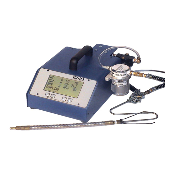
Figure 1 highlights the features and buttons available on the Model 5002 front display area. The HC will display up to five digits and is in ppm, CO is in percentage, CO2 is in per- centage, and NOX is in ppm.O2 is in percentage and you can change to either LAMBDA or... -
Page 5: Button Operation Model 5002
Button Operation Model 5002 Figure 2 Figure 2 shows the control buttons on the front of the gas analyzer: The “Zero” button has two functions. a. Zeroing the gas analyzer as needed during use. b. Restarting the pump following automatic shutdown. -
Page 6: Rear Panel Description
NOTE: The standard EMS filter arranegement has been changed and must be upgraded. Sample Hose Connection: The sample hose connection uses a quick disconnect coupler. -
Page 7: Gas Analyzer Preparation
Note: This description applies to the Model 5002 analyzer with a display, see Page 16 for instructions on setting up a Model 5002-W & 8000 bluetooth wireless analyzer. The first step is assembling the sample hose. Once the sample hose is assembled, connect the hose to the sample hose fitting on the back of the analyzer. -
Page 8: Gas Analyzer Operation
Gas Analyzer Operation Immediately after applying power, the analyzer will display EMS warming up (Figure 9) for a set amount of time. This starts the analyzer warm-up mode and will continue for approxi- mately 5 to 10 minutes, depending on ambient temperature. Once the warm-up mode is com- plete, the analyzer will go into the “ZEROING”... - Page 9 Gas Analyzer Operation Manual Zero: Any time after warm-up, you can zero the gas readings and calibrate O2 by pressing the “ZERO” button (Figure 13). When this operation is being done “ZEROING” will be displayed (Figure 14). The analyzer will shut down automatically if no CO2 is detected after approx.
- Page 10 The analyzer can be connected to a PC using a 9 pin serial communications cable (DB9). EMS offers software that will display the sample gases, graph data and record informa- tion. Using the portable gas analyzer with a laptop will help diagnose problems that only occur...
-
Page 11: Calibration
(Figure 18). The calibration assembly can be purchased from EMS or your local distributor. The recommended calibration gas is Bar 97 Low and can be purchased from EMS, Part No.EMS-5502, BAR 97 LOW Figure 18 Calibration Procedure: 1. - Page 12 “HC or CO or CO2 C Warn”. Go back to the main sampling screen and “ZERO” the unit to clear the error. After either situation, perform the calibra- tion procedure again. If the problem continues, contact EMS or your local distributor. NOTE: The hydrocarbon gas in the calibration cylinder is propane, and the gas ana- lyzer generally measures hexane.
-
Page 13: Error Messages
ERROR MESSAGES If the optical bench detcts any errors during operation, a message will be displayed on the sampling screen “SEE ERRORS” (Figure 25). If this message comes up, depress the menu button, and the main menu screen will be displayed (Figure26). Depress the “errors button” and the errors screen will be displayed (Figure 27). -
Page 14: Maintenance
If this does not occur a leak is present in the sys- tem. Check the sample hose for leaks first, check the external filter next and finally the internal hoses. Contact EMS or your local distrubutor for assistance if required. 2. The External Filter should be checked often (Figure 29 NOTE: This filter has been dis- continued as of Aug 2017 see pg. - Page 15 Maintenance Internal Analyzer Maintenance: The maintenance items discussed below are located inside the analyzer. The outside cover will need to be removed to gain access. The cover is held in place with 12 screws, 5 on each side panel and two at the top behind the handle. 3.
- Page 16 3 months. To determine the correct replacement interval for your shop, check the filter once a month (EMS-5070). The water trap filter is the same coalescing filter (Figure 35; EMS-5372) with the sample gas flow from inside out, so NO contamination can be visibly seen as with the external filter.
- Page 17 3 months. To determine the correct replacement interval for your shop, check the filter once a month (EMS-5070). The water trap filter is the same coalescing filter with the sample gas flow from inside out, so NO contamination can be visibly seen as with the external filter.
- Page 18 Make sure the filter goes on straight, this is the most common point for leaks! Screw on filter bowl turning counterclockwise. Do a leak check after any filter change. 3) O2 Sensor; part #: EMS-5060; 12-18 month (1- 1 1/2 Year) Interval or ERROR code C WARN 5002 model. ·...
- Page 19 Maintenance 4) NOX Sensor; part #: EMS-5065; 6 month min. re-calibration for accuracy and 2-3 Year Interval change out, or ERROR code NOX Z WARN 5002 model. · NOX Sensors should re-calibrated a min of 6 month intervals. New NOX sen- sors require re-calibration as well as NOX accuracy checks.
- Page 20 30 seconds. · Leak check failures would be if the 5002 model pumps turn on during the 30 sec- onds. The most common leak location is at the external filter head, this can be check with a butane lighter to see if your HC reading increases. Make sure the filter is screwed on straight and the O-Ring is moistened.
- Page 21 The separator will work better in colder weather, to enhance the capability of the separator in hot humid weather, EMS recommends to make a home made oil/water condenser to cool the sample with a simple ice bath. This can be done with a plastic cup filled with ice around the reservoir.This simple trick will be very effective...
- Page 22 Oil/Water Separator with Can Cooler Ice Bath · Diesel Testing when Urea is used to reduce NOX (SCR) : The EMS analyzer is fully capable of diesel testing. Your HC reading will only be accurate for Hex- ane gas, so a Smoke/Opacity meter would be required to check PM. All other gases will be accurate including NOX.
- Page 23 USB to Serial Adapter 13" EMS-5258 DB9 Serial Cable 6 ft Long EMS-5259 DB9 Serial Cable 15 ft. Long EMS-5098-1/4-20 Exhaust Probe 1/4-20 Threaded End EMS-5099 EVAP/Small Engine/Motor Cycle Probe EMS-5151 Small Body Oil/Water Separator EMS-5093-CS Inline Absorber Filter for Diesel/Urea EMS-5370 External Filter Bowl.
-
Page 24: Diagnostic Accessories & Diagnostics
EVAP Probe EMS also offers a pop nut insert tool kit (Fig.4) for the pre-cat probe w/ a 1/4”-20 threaded end. The kit includes the pop nut insert tool, 1/4-20 mandrel, box of 40 nuts, 50 pc’s 1/4- 20x3/8” stainless steel SHCS, 25/64” drill bit The EMS EVAP probe,( small engine) (Fig. 5) is 3/16”... - Page 25 Diagnostics Exhaust gas analyzers can be used to diagnose driveability concerns, ignition system prob- lems, fuel management issues, engine mechanical problems, excessive emissions problems and many other vehicle systems. Vehicle inspection and preparation are the keys to getting the most out of your gas analyzer. 1.
-
Page 26: Warranty
Your particular problem may be covered in the operating instruc- tions. If the issue cannot be resolved, contact EMS or your authorized distributor for additional information. If the unit requires repair, contact EMS to obtain a Re- turn Authorization Number. The unit should be properly packaged and should include all accessories.
Need help?
Do you have a question about the 5002 and is the answer not in the manual?
Questions and answers