Table of Contents
Advertisement
Quick Links
Advertisement
Table of Contents

Related Manuals for Roadmaster Sterling ALL-TERRAIN 576


Summary of Contents for Roadmaster Sterling ALL-TERRAIN 576
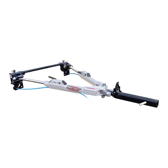
- Page 1 ® 2007-2021 ROADMASTER, Inc. All rights reserved. 853326-31 09-21...
-
Page 2: Table Of Contents
All illustrations and specifications contained herein are based on the latest information available at the time of publication. ROADMASTER, Inc. reserves the right to make changes, at any time, without notice, in material, specifica- Serial number: tions and models, or to discontinue models. -
Page 3: Safe Towing Practices
Failure only. ROADMASTER does not recommend off-road tow- to properly equip the vehicle will cause severe damage ing, nor does ROADMASTER warrant the tow bar for off- to the transmission. road use. - Page 4 Safe towing practices continued from preceding page Failure to follow these instructions may cause non • Do not drill a second hole in the shank of any tow -warranty property damage, personal injury or even bar or hitch accessory. If the hole in the shank does death.
-
Page 5: Connecting The Tow Bar
CONNECTING THE TOW BAR the baseplate (Figure 4 — next page). Attach the tow bar arm to the baseplate with one of Use caution when handling the tow bar — if your the included base pins (Figure 4). Attach the arm so that hands, fingers or any part of your body are caught the head of the shoulder bolt (Figure 4) is facing up. - Page 6 Connecting the tow bar continued from preceding page Figure 4 STEP 6 baseplate shoulder bolt head must face up linch pin base pin side view If the spring-loaded ring on the linch pin does not snap against itself, spin the linch pin around and flip the ring to the other side.
-
Page 7: Disconnecting The Tow Bar
ROADMASTER recommends replacing at least one of base pins. Failure to do so may result in a ‘runaway’ the linch pins with a padlock (part number 301, 302 or vehicle or may crush you between the towed vehicle 308) to prevent accidental release or theft. -
Page 8: Wiring Instructions
2. Strip ¼" to 3/8" of insulation from the ends of the wires. Loosen the set screw at the back of the socket and push Socket Roadmaster Motorhome/ the inner connector out the front. Then run the six-wire Number Code... -
Page 9: Safety Cables
If the cables are too short, the towing system will be severely damaged when the motorhome turns a sharp corner. (Safety cable extensions in a variety of lengths are available from ROADMASTER.) -
Page 10: Proper Installation Of Safety Cables
PROPER INSTALLATION OF SAFETY CABLES Cross the safety cables under the hitch receiver, as shown in Figure 9. Option 2 Option 1 If the tow bar baseplate has removable arms and your If the tow bar baseplate is similar to the one shown safety cables are not long enough to bypass them, then in Figure 9 and the safety cables are long enough, con- connect as shown in Figure 10 using short safety cables... -
Page 11: Stay Within The 'Safe Zone
Towing with the tow bar more than three inches above first, connect the motorhome and towed vehicle on level or below level will void the ROADMASTER warranty. ground. Next, measure the distance from the center of the motorhome receiver down to the ground. Then, measure... - Page 12 STERLING ALL TERRAIN COMPONENTS Please have your serial number handy when calling for repair parts, as not all versions of this tow bar use the same parts. part part description number description number baseplate arms (not included) 2 base pin, cable and linch pin inner arm assembly, driver's (two each;...
Need help?
Do you have a question about the Sterling ALL-TERRAIN 576 and is the answer not in the manual?
Questions and answers