Table of Contents
Advertisement
Quick Links
Advertisement
Table of Contents

Related Manuals for Roadmaster All Terrain Sterling


Summary of Contents for Roadmaster All Terrain Sterling
- Page 1 Owner’s Manual Entire contents of manual must be read by owner Towing and Suspension Solutions ROADMASTER, Inc. • 6110 NE 127th Ave. • Vancouver, WA 98682 800-669-9690 • Fax 360-735-9300 • roadmasterinc.com © 2010 ROADMASTER, Inc. All rights reserved. 853326-06 09-10...
-
Page 2: Table Of Contents
WELCOME TO THE ROADMASTER FAMILY! This manual has been prepared to acquaint you with the installation, operation, care and maintenance of your tow bar, and to provide you with important safety information. Read your owner’s manual cover to cover. Understand how to install and operate your tow bar, and carefully follow the instructions and safety precautions. Your tow bar has a one-year limited warranty. To qualify for your warranty, fill out and return the enclosed product registration card within 30 days of purchase. As a bonus, we’ll extend your warranty to a total of two years at no... -
Page 3: Safe Towing Practices
SAFE TOWING PRACTICES ing in “jackknifing,” “leapfrogging” or “fishtailing.” Serious damage to both vehicles, as well as the towing system, • Do not back up the motorhome with the towed ve- could result. hicle attached. • Always stand to one side and as close to the motor- Backing up with the towed vehicle attached will home as possible when releasing the tow bar locking cause the towed vehicle to “jackknife,” which will dam- mechanisms. Never stand between the adjustable arms, age the tow bar, the mounting bracket, the receiver or put any part of your body between the adjustable arms, hitch, the towed vehicle’s front end, and/or the rear when releasing the tow bar — always stand to one side. -
Page 4: Installer's Safety Checklist
Note: the quick-disconnect system is not used with Do not tighten any of the bolts — leave them loose for ROADMASTER ‘MS’ or ‘MX’ series mounting brackets. now — they will be tightened later. If the towed vehicle has MS or MX brackets, proceed to the next section — “Connecting the tow bar.” The quick-... -
Page 5: Installing The 'Quick-Disconnect' System
Installing the ‘quick-disconnect' system Both linch pins must be locked. The rings (Figure 3) are spring-loaded — they must be snapped over the pins, continued from preceding page of the crossbar (Figure 2), and the vertical pins at the as shown in Figure 3, with the curved side of the linch bottom of the crossbar should fit through the lower holes pin touching the ring, in order to keep the QD bases on the quick-disconnects (Figure 2). -
Page 6: Connecting The Tow Bar
Note: the quick-disconnect system is not used with ROADMASTER ‘MS’ or ‘MX’ series mounting brackets. Instead, the tow bar is connected directly to the mounting bracket with the base pins and linch pins. With this exception, the instructions below apply. -
Page 7: Disconnecting The Tow Bar
(under “Connecting the tow 2. Disconnect the electrical wiring harness, safety cables, bar”). and any other towing system accessories. ROADMASTER recom- 3. Lift the release handles on each tow bar arm (Figure mends replacing at least 9) to release the locking mechanisms. one of the linch pins with a padlock (part number 301, 302 (Usually, one of the handles will require more pressure or 308) to prevent accidental release or theft. to release. This is the arm that has the majority of the tension between the two vehicles.) -
Page 8: Wiring Instructions
3. Strip ¼" to 3/8" of insulation from the ends. Connect the wires according to Figure 10; apply a silicone sealant to plug Figure 10 the attachment points to help prevent damage from moisture front of and corrosion. 4-wire plug Wiring the socket for a four-wire system S ocket Pin Roadmaster Motorhome/ Number 4-wire color Towed Vehicle 1. If necessary, find a suitable location to install one of the 1 ..Yellow .....Left turn/stop electrical socket brackets on the front of the towed vehicle, 2 ..White ....Ground in reach of the existing four-wire harness. The bracket must 3 ..Red ....Right turn/stop 4 .. -
Page 9: Wiring A Seven-Wire System
Socket Wiring the plug for a seven-wire system Roadmaster Roadmaster Motorhome/ Number 4-wire color... -
Page 10: Safety Cables
• The safety cables must be the correct length… • Some ROADMASTER tow bar mounting kits with re- • Make sure the cables are not too short — if you use a movable arms use two safety cables on each side. If two receiver hitch extension or other equipment that extends sets of safety cables are required, both must be used. This the distance between the towed vehicle and the motor- is required by law. Refer to “Proper installation of safety... -
Page 11: Proper Installation Of Safety Cables
PROPER INSTALLATION OF SAFETY CABLES Figure 17 Figure 16 replace the cables. Some ROADMASTER tow bar mounting brackets with Failure to follow these instructions will result in removable arms, such as the ones in Figures 16 and 17, use both a long safety cable and a short safety cable on cable failure, which may cause property damage, per- each side. sonal injury or even death. -
Page 12: Stay Within The 'Safe Zone
Towing a vehicle with a tow bar that is not within the purchase a hitch accessory to raise or lower the hitch Safe Zone will result in significant wear and tear on the receiver. ROADMASTER has three accessories available tow bar and brackets, significant wear and tear on the — Hi-Low Hitches, Hi-Low Drops, and Dual Hitch Receiv- vehicle’s suspension and frame, and the eventual failure... -
Page 13: Limited Warranty
1. WARRANTY in the repair or replacement. If ROADMASTER repairs or replaces a product, 1a. WARRANTY OF CONFORMITY AT TIME OF SALE its warranty continues for the remaining portion of the original Warranty Period ROADMASTER, Inc. warrants that at the time of sale of this product it or 60 days from the date of the return shipment to the customer, whichever is will be free from defects in material and manufacture and will conform to greater. All replaced products and all parts removed from repaired products ROADMASTER’S specifications for the product. - Page 14 — — advertisement We’re the suspension experts ery few people would say they bought their The primary benefits of ROADMASTER motorhome (or truck, van or SUV) for the sus- suspension components are… • Anti-sway bars — virtually eliminate ‘body roll’ (the pension. For most of us, the suspension is out of sight and out of mind — even though your driving...
- Page 15 — advertisement We’re the suspension experts Reflex Steering Stabilizers continued from preceding page Which component is right for you? Your best insurance against the catastrophic con- ROADMASTER designs, engineers and manufactures sequences of a front tire blow out is a Reflex Steer- anti-sway bars, trac bars, and steering stabilizers for both ing Stabilizer. original equipment manufacturers and the aftermarket. When you blow out a front tire, your vehicle will Anti-sway bars, trac bars and steering stabilizers work make an abrupt turn toward that tire, causing you to in concert with the other components of your suspension veer into oncoming traffic or off the road. The Reflex...
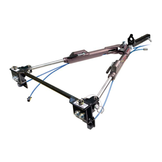
- Page 16 STERLING ALL TERRAIN COMPONENTS Please have your serial number handy when calling for repair parts, as not all versions of this tow bar use the same parts. part part description number description number 1 quick-disconnects, complete 9 yoke assembly with bushing car side set (color-coded red) ........222 (color-coded red; part numbers 1a linch pins (two) ..........910024 9a through 9e sold separately) ......910575 2 safety cable anchor brackets, complete set — 9a ¾" x 4¾" bolt ...........350190-20 driver's and passenger side 9b ¾" jam nut ..........350264-10 (color-coded black) ..........
Need help?
Do you have a question about the All Terrain Sterling and is the answer not in the manual?
Questions and answers