Table of Contents
Advertisement
Quick Links
Advertisement
Table of Contents

Subscribe to Our Youtube Channel
Related Manuals for Roadmaster 9700


Summary of Contents for Roadmaster 9700
- Page 1 Owner’s Manual Entire contents of manual must be read by owner Part number 9700 Time Tested • Time Proven ROADMASTER, Inc. • 6110 NE 127th Ave. • Vancouver, WA 98682 800-669-9690 • roadmasterinc.com 853602-06 05/18 © 2006-2018 ROADMASTER, Inc. All rights reserved.
-
Page 2: Safety Definitions
Your 9700 has a one-year limited warranty. To qualify for your warranty, fill out and return the enclosed product registration card within 30 days of purchase. As a bonus, we’ll extend your warranty to a total of two years at no additional cost, if we receive the product registration card within 30 days of purchase. -
Page 3: Table Of Contents
MASTER supplemental braking system other than CAUTION BrakeMaster; or 2) failure to install a Brake Pres- Do not install the 9700 in a vehicle with an ‘ac- sure Reducer with the BrakeMaster. tive’ braking system. ‘Active’ (or, ‘continuous power assist’) braking... -
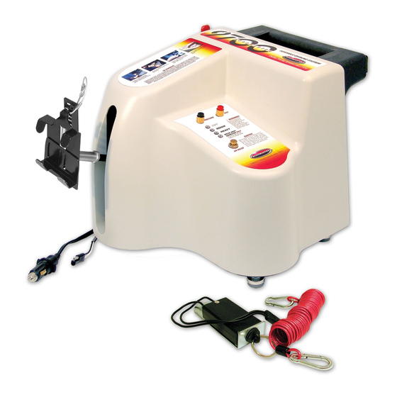
Page 4: Components
COMPONENTS part number description part number description 1 9329 ....brake pedal clamp 10 650906....wiring harness 2 n/a .......air cylinder shaft 11 650900....break away wiring harness 3 n/a .......brake pressure button 12 8602 ....break away cable 4 n/a .......test button 13 650898....break away switch 5 n/a .......air relief button 14 650906-01 ...brake signal wire 6 650996....adjustable seat pad... -
Page 6: Before You Begin The Initial Installation (Installer's Checklist)
NO LESS THAN 15 AMPS to power battery disconnected. the 9700. Check the fuse at the outlet — if the fuse is If you choose to install the battery disconnect, a rated at 15 amps or higher, the circuit is adequate to brake light switch is still required;... - Page 7 — diodes must be attached to the wires. The electrical circuit that turns the towed vehicle's brake lights on and off also turns the 9700 on and off. If diodes are not attached, electrical feedback through the brake light wire will prevent the 9700 from releas- ing braking pressure.
-
Page 8: Initial Installation
2. The break away wiring harness (Figure 1) connects the break away switch to the 9700. It will be routed through the firewall, on the driver’s side. Look for a pre-existing hole in the firewall (or, if there... -
Page 9: Install The Motorhome Monitor
LED on the motorhome …one of the three alternatives below is required. dashboard will illuminate each time the 9700 is acti- A. A system of diodes vated, confirming that the towed vehicle’s brakes have Figure 2 (the vehicle’s turn sig-... -
Page 10: Attach The Brake Signal Wire
When Trim the protective covering over the electrical cable; the brake signal wire is connected to the 9700 (along wrap any exposed wiring with electrical tape. with the other components of the braking system), the... -
Page 11: Attach The Firewall Grommet; Attach The Wiring Connectors
2d. If the towed vehicle has a bulb and socket (“taillight”) 2. When the 9700 is connected and disconnected, the wiring kit… 9700 wiring harness will be plugged into and out of the • Make certain that a ground connection exists be- connectors on the break away wiring harness and the tween the towed vehicle and the motorhome. -
Page 12: Test The Braking System
6. From the top of the dashboard, slide the LED 1. Connect the 9700 according to the instructions in the through the hole, wires first, until the base of the bulb next section in this manual — “Day-to-day operation.”... -
Page 13: Initial Installation
If the LED does not illuminate… …it may indicate that the 9700 is wired incorrect- ly. If the 9700 is wired incorrectly, it will not brake the towed vehicle in tandem with the motorhome. Insufficient braking pressure will lengthen stopping distance, and may also cause a loss of vehicular control. -
Page 14: Day-To-Day Operation
Always deplete the vacuum in the vehicle’s power brake system BEFORE YOU RESUME TOWING. If the vacuum is not released, the 9700 will apply excessive force when it is activated, which will cause severe tire and/or brake system damage to the towed vehicle. Refer to the caution statement on page 19 for further information. -
Page 15: Attach The Pedal Clamp
If the tabs are loose, the pedal clamp can rotate out of position and hold the brake pedal down, even when the 9700 is not activated, which will cause brake damage or other consequential, non-warranty dam- age. -
Page 16: Adjust The Feet And The Seat Pad
Figure 9 Adjust the feet and the seat pad 1. Now that the pedal clamp is in place, move the 9700 forward, until the air cylinder shaft is fully retracted (Figure 9). Make certain that the 9700 is not depress- ing the towed vehicle’s brake pedal. -
Page 17: Plug In The Power Cord
Before towing, always press the “Test” button down, CAUTION then release it — the 9700 will cycle the pedal clamp Check the 12-volt outlet socket before plugging up and down three times. in the 9700 12-volt power cord, to make certain This test cycle is necessary for two reasons: 1) to that the socket has been wired correctly. -
Page 18: Set The Brake Pressure
The brake pressure setting is the amount of force the Selecting “Break Away Condition Only” restricts 9700 will apply to the towed vehicle’s brakes — after the the 9700 to an emergency break away response only. In this mode, the 9700 will not brake the towed motorhome brakes are applied, the 9700 will brake the towed vehicle with either “light,”... -
Page 19: Connect The Motorhome Monitor Patch Cord
Additionally, the 9700 compressor will run con- …at any time when the motorhome brake pedal stantly, which will damage the compressor and is depressed, it may indicate that the 9700 is not drain the vehicle’s battery. functioning. If the 9700 is not functioning, it will... -
Page 20: Protection Modes
An incorrect flasher speed may activate the 9700 unnecessarily, causing excessive brake wear or PROTECTION MODES he 9700 has two built-in safeguards to protect the towed vehicle’s brakes. These protection modes are described below. Extended braking protection Responding to an audio alert To protect the towed vehicle’s brakes, the 9700 will... -
Page 21: Quick Reference Checklist
9700 to the towed vehicle; see the next page to disconnect the 9700. For more detailed information, refer to the appropriate section under “Day-to-day operation.”... -
Page 22: Disconnecting The 9700
4. Press and hold the air relief button (Figure 5) until all the air in the air reservoir is released. If necessary, continue to hold the air relief button and move the 9700 back, to allow easier access to the brake pedal. -
Page 23: Troubleshooting
The 9700 “climbs” up the seat. • If there is a rubberized floor mat under the 9700, remove it during tow- ing. • Check the position of the adjustable seat pad. The seat pad serves as an anchor point, to keep the 9700 down as it presses the brake pedal. - Page 24 9700 activates. • Verify that the 9700 is receiving a brake light signal from the motorhome — with a test light, check for voltage at the female bullet connector (at the end of the green brake signal wire) which is plugged into the 9700 wiring harness.
-
Page 25: Ford 'Neutral Tow' Vehicles
CAUTION To wire the vehicle for towing… If the 9700 is to be installed in any Ford vehicle There are three methods available which will allow with a ‘neutral tow’ kit, do not install a Brake-Lite a towed vehicle’s turn signals, brake lights and running... -
Page 26: Ford 'Neutral Tow' Vehicles
FORD ‘NEUTRAL TOW’ VEHICLES To wire the vehicle for towing… vehicle’s turn signals will not operate in conjunc- tion with the motorhome’s turn signals, as required continued from preceding page arate circuits, a 3-to-2 converter has not been installed. by law. 2. -
Page 27: Optional Equipment
Although the 9700 fits most vehicles as is, with no modifications needed, it may be necessary to gain additional clearance over obstructions on the floor, or to extend the reach of the 9700 to ensure a secure and stable fit. The air cylinder shaft extensions increase the reach of the 9700. -
Page 28: Limited Warranty
In addition to the preceding time-of-sale warranty, if the shipping, freight, taxes, or other incidental charges. product registration card is completely and accurately filled out and mailed to ROADMASTER within thirty (30) days of THESE REMEDIES ARE THE EXCLUSIVE AND SOLE purchase, ROADMASTER will provide an additional war- REMEDIES FOR ANY BREACH OF WARRANTY. -
Page 29: Index
......12, 15, 19 Air cylinder shaft Power cord — plugging in ......... 15 Positioning when connecting the 9700 ....14 Safety definitions ......inside front cover Air relief button ............12 Second vehicle kit — description ......25 Audio alert —... - Page 30 • …is designed as a custom fit, for a specific chassis. out? • Does the steering wheel have a mind of its own? ROADMASTER engineering designs take into consid- • Do passing 18-wheelers and crosswinds rock your eration chassis and axle manufacturers’ specifications vehicle back and forth? (your warranty will not be affected).
- Page 31 — is just a few bolts motorhome handles like a sports car. The stabilizer away. Anti-sway bars from Roadmaster Suspension keeps the steering centered, no matter what the road Solutions deliver a “Wow!” difference in RV control throws at me.
- Page 32 All illustrations and specifications contained herein are based on the latest information available at the time of pub- lication. ROADMASTER, Inc. reserves the right to make changes, at any time, without notice, in material, specifica- tions and models, or to discontinue models.
Need help?
Do you have a question about the 9700 and is the answer not in the manual?
Questions and answers
My road master 9700 braking system is losing air pressure quickly. Pump runs about every 60 seconds. I can hear hissing coming from below the buttons. Can I get internal parts?
Yes, internal parts for the Roadmaster 9700 Portable Braking System are available for purchase. A parts list is provided, and individual components such as the brake pedal clamp and adjustable seat pad are listed with part numbers.
This answer is automatically generated
@Mr. Anderson I see the parts list that you sent me but not of the internal components. Mine is leaking air inside the cover.