Fujitsu MB95200H Series Setup Manual
Hide thumbs
Also See for MB95200H Series:
- Application note (12 pages) ,
- Application note (12 pages) ,
- Operation manual (18 pages)

Related Manuals for Fujitsu MB95200H Series


Summary of Contents for Fujitsu MB95200H Series
- Page 1 FUJITSU MICROELECTRONICS MCU-UM-500002-E-11 SUPPORT SYSTEM F²MC-8FX FAMILY 8-BIT MICROCONTROLLER MB95200H/210H SERIES STARTER KIT MB2146-410-01-E SETUP GUIDE...
-
Page 3: Handling And Use
For mass production/evaluation MCUs for this product, consult with sales representatives or support representatives. *1: F2MC is the abbreviation of FUJITSU Flexible Microcontroller. *2: Referred below as the “Starter Kit”. *3: Referred below as the “BGMA”. -
Page 4: Caution Of The Products Described In This Document
Starter Kit MB2146-410-01-E Setup Guide V1.1 PREFACE ■ Caution of the products described in this document The following precautions apply to the product described in this manual. Indicates a potentially hazardous situation which, if not avoided appropriately, WARNING could result in death or serious injury and/or a fault in the user’s system. Electric shock, Before performing any operation described in this manual, turn off all the power supplies to the system. - Page 5 The information, such as descriptions of function and application circuit examples, in this document are presented solely for the purpose of reference to show examples of operations and uses of FUJITSU MICROELECTRONICS semiconductor device; FUJITSU MICROELECTRONICS does not warrant proper operation of the device with respect to use based on such information.
-
Page 6: Table Of Contents
Starter Kit MB2146-410-01-E Setup Guide V1.1 Contents Contents PREFACE ........................i Handling and use ......................i ■ Notice on this document....................i ■ Caution of the products described in this document ............ii ■ Contents........................iv PRODUCT OVERVIEW ....................1 Objective and Deliverable..................1 System Block ...................... -
Page 7: Contents
Starter Kit MB2146-410-01-E Setup Guide V1.1 Contents 4.3.2 Startup.asm File..................19 4.3.3 Vectors.c File................... 19 4.3.4 Main.c File ....................20 DEVELOPMENT PLATFORM QUICK START ............21 Tools Setup Sequence ..................21 Open Project and Start Debug................21 Operation Precautions................... 21... -
Page 9: Product Overview
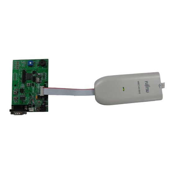
Starter Kit MB2146-410-01-E Setup Guide V1.1 Chapter 1 Product Overview Product Overview This product is a set of Starter Kit (MB2146-410-01-E) of MB95200H/210H series. It is composed of a BGMA (MB2146-08-E) and an EV-board (MB2146-410-E). Combining the SOFTUNE Workbench on PC, the Starter kit enables the quick start of development before the user system is ready. -
Page 10: Feature
Starter Kit MB2146-410-01-E Setup Guide V1.1 Chapter 1 Product Overview 1.4 Feature The F2MC-8FX starter kit is the best for a performance and functional evaluation, and a check of operation before including F2MC-8FX in a user's system. Below, the feature of the BGM debugger for F2MC-8FX is shown. Microcomputer operation voltage It corresponds to +2.7V to +5.5V. -
Page 11: Bgma Manual
Starter Kit MB2146-410-01-E Setup Guide V1.1 Chapter 2 BGMA Manual 2 BGMA Manual This chapter gives introduction how to setup BGMA. 2.1 BGMA Overview Below is the close look of the BGMA. The Part Number of the MB95200H/210H BGMA is MB2146-08-E. -
Page 12: Idc10 Interface Description
Starter Kit MB2146-410-01-E Setup Guide V1.1 Chapter 2 BGMA Manual 2.3 IDC10 Interface Description Pin Number Pin Name Description UVCC Target MCU Vcc Target MCU Vss RSTIN Target MCU reset input RSTOUT Target MCU reset output Reserved Reserved Reserved Target MCU debug pin Reserved Reserved 2.4 BGMA USB Configuration... - Page 13 Starter Kit MB2146-410-01-E Setup Guide V1.1 Chapter 2 BGMA Manual Select “Install from a list or specific location (Advanced)”, then click “Next”, Figure 2.4-2 Install BGMA in Windows (2) Select “…\Drivers” from the folder where SOFTUNE is installed, click “Next”, Figure 2.4-3 Install BGMA in Windows (3) MCU-UM-500002-E-11 –...
- Page 14 Starter Kit MB2146-410-01-E Setup Guide V1.1 Chapter 2 BGMA Manual Select BGMA (MB2146-08) as displayed below, and then click “Next”, Figure 2.4-4 Install BGMA in Windows (4) Windows will install the driver automatically. Click “Finish” after the driver has completed the installation normally.
-
Page 15: Led Description
Starter Kit MB2146-410-01-E Setup Guide V1.1 Chapter 2 BGMA Manual 2.5 LED Description First, only plug USB cable to PC, check the Power LED on BGMA turns Green. Refer to Figure 2.5-1. Green USB Plugged to PC Figure 2.5-1 BGMA Power LED (1) Second, plug IDC10 cable to the EV-board (target MCU board), then turn on EV-board. -
Page 16: Ev-Board Manual
Starter Kit MB2146-410-01-E Setup Guide V1.1 Chapter 3 EV-board Manual 3 EV-board Manual This chapter gives introduction how to setup EV-board. 3.1 EV-board Overview MB95200H/210H MCU EV-board is provided as a user-friendly introductory and evaluation platform for the MB95200H/210H MCU Family microcontroller. Figure 3.1-1 below is a close look of EV-board. -
Page 17: Function List
Starter Kit MB2146-410-01-E Setup Guide V1.1 Chapter 3 EV-board Manual 3.2 Function List The EV-board consists of a board and a sample firmware. The board provides a useful platform for using the MCU and its peripherals. It is a useful development platform together with a BGMA (PN: MB2146-08-E) and a SOFTUNE. -
Page 18: Ev-Board Schematic
Starter Kit MB2146-410-01-E Setup Guide V1.1 Chapter 3 EV-board Manual 3.3 EV-board Schematic Figure 3.3-1 EV-board Schematic MCU-UM-500002-E-11 – Page 10... -
Page 19: Hw Module Description And Jumper Settings
Starter Kit MB2146-410-01-E Setup Guide V1.1 Chapter 3 EV-board Manual 3.4 HW Module Description and Jumper settings 3.4.1 Power Module Users can select two types of DC power supply to the EV-board. If any of the power supplies is connected to the EV-board correctly, power LED (LED5) on the EV-board will be on. Refer to Figure 3.4.1-1. -
Page 20: Bgma Interface
Starter Kit MB2146-410-01-E Setup Guide V1.1 Chapter 3 EV-board Manual 3.4.2 BGMA Interface To start the debug using a BGMA, users shall connect IDC10 socket from the BGMA to CN1 on an EV-board, and J2 shall be open in a debug mode. In a normal (free-run) mode, J2 shall be closed to enable reset key S3. -
Page 21: A/D Module
Starter Kit MB2146-410-01-E Setup Guide V1.1 Chapter 3 EV-board Manual 3.4.5 A/D Module VR1 and VR3 are to demonstrate a MCU A/D converter usage. Select VR1 or VR3 by the following table. VR1 is connected to MCU A/D channel 1, and VR3 is connected to MCU A/D channel 0. Modules Header name Settings... -
Page 22: Key Module
Starter Kit MB2146-410-01-E Setup Guide V1.1 Chapter 3 EV-board Manual 3.4.7 Key Module Key S1 and key S2 are provided to demonstrate an external interrupt function. Enable these two keys by the following table. Key S1 is connected to external Int7, and key S3 is connected to external Int6. Modules Header name Settings... -
Page 23: Sample Code Manual
Starter Kit MB2146-410-01-E Setup Guide V1.1 Chapter 4 Sample Code Manual 4 Sample Code Manual 4.1 Topic List The following sample codes are provided with MB95200H/210H MCU Starter Kit, IO_LED project In this example, the 3 LEDs will be on in the following sequence: ...->LED2->LED3->LED4... - Page 24 Starter Kit MB2146-410-01-E Setup Guide V1.1 Chapter 4 Sample Code Manual LIN master In this example, the MCU is running in a Lin Master mode. After a reset, the MCU starts sending data to a Slave. If the Master gets correct data from the Slave, the MCU restarts sending.
-
Page 25: Project Structure
Starter Kit MB2146-410-01-E Setup Guide V1.1 Chapter 4 Sample Code Manual 4.2 Project Structure The Sample code is organized by the following structure in each project. Here take IO_LED project for example shown in Figure 4.2-1. Figure 4.2-1 I/O_LED Project Structure MCU-UM-500002-E-11 –... -
Page 26: Source Code File Description
Starter Kit MB2146-410-01-E Setup Guide V1.1 Chapter 4 Sample Code Manual 4.3 Source Code File Description Six files are available in each sample code source code folder shown below, Figure 4.3-1 Source Code Files 4.3.1 Header Files The MB95200H/210H.h and the MB95200H/210H.asm are header files, including MB95200H/210H MCU I/O registers definition;... -
Page 27: Startup.asm File
Starter Kit MB2146-410-01-E Setup Guide V1.1 Chapter 4 Sample Code Manual #define PDR0_P03 _pdr0.bit._P03 #define PDR0_P04 _pdr0.bit._P04 #define PDR0_P05 _pdr0.bit._P05 #define PDR0_P06 _pdr0.bit._P06 #define PDR0_P07 _pdr0.bit._P07 In MB95200H/210H.asm, PDR0 address 0x0000 is allocated to PDR0 as below. __pdr0 .res.b 1 ;000000 /* Port0 */ PDR0 .equ 0x0000... -
Page 28: Main.c File
Starter Kit MB2146-410-01-E Setup Guide V1.1 Chapter 4 Sample Code Manual 4.3.4 Main.c File Main.c contains the user code. MCU-UM-500002-E-11 – Page 20... -
Page 29: Development Platform Quick Start
Starter Kit MB2146-410-01-E Setup Guide V1.1 Chapter 5 Development Platform Quick Start 5 Development Platform Quick Start 5.1 Tools Setup Sequence Start the debugging system in the following sequence: Connect a BGMA to the PC using a USB cable, confirm the LED on the BGMA is Green; Connect an EV-board to BGMA IDC10 socket;... - Page 30 MCU-UM-500002-E-11 FUJITSU MICROELECTRONICS LIMITED • SUPPORT SYSTEM F2MC Family Starter Kit MB2146-410-01-E SETUP GUIDE April 2008 the second edition Published FUJITSU MICROELECTRONICS LIMITED Edited Business Promotion Dept.
Need help?
Do you have a question about the MB95200H Series and is the answer not in the manual?
Questions and answers