
Related Manuals for Fujitsu UTB-YCA


Summary of Contents for Fujitsu UTB-YCA
- Page 1 SETTING MANUAL CENTRAL REMOTE CONTROLLER UTB-YCA UTB-GCA Before using this controller, please read this [SETTING MANUAL] to ensure correct operation. Keep this manual for future reference.
-
Page 3: Table Of Contents
CONTENTS 1. SAFETY PRECAUTIONS .............. 2 2. SYSTEM OUTLINE ............... 3 2-1. SYSTEM OUTLINE ................3 2-2. EXPLANATION OF TERMS ..............5 2-3. NAMES AND FUNCTIONS OF THE PARTS ........8 2-4. PRECAUTIONS WHEN SETTING THE SYSTEM ......10 2-4-1. Priority of remote controller setting ............ -
Page 4: Safety Precautions
1. SAFETY PRECAUTIONS • Before using CENTRAL REMOTE CONTROLLER, read this “SAFETY PRECAUTIONS” thor- oughly to ensure the correct operation. • This section discribes the important safety information to operate CENTRAL REMOTE CON- TROLLER. • The meanings of “WARNING” and “CAUTION” are explained as follows. This mark indicate procedures which, if improperly performed, are most WARNING! likely to result in the death of or serious injury to the user or service per-... -
Page 5: System Outline
2. SYSTEM OUTLINE 2-1. SYSTEM OUTLINE Group Controller line Tr ansmission line Refrigeration system 1 50Hz 220 - 240V 4W 50Hz 380 - 415V Indoor unit 50Hz 220 - 240V Centr a l remote controller Remote Controller Group Please consult your sales representative when two or more central remote controllers need to be installed in one system. - Page 6 • Three control methods of the central remote controller • Individual control Provides control for each respective remote controller group. • Group control Provides control for each group which is made up of single or multiple previously set remote control groups. (Refer to “2-3.
-
Page 7: Explanation Of Terms
2-2. EXPLANATION OF TERMS Controller related items Remote controller group Group Transmission line Outdoor unit Refrigerant system Indoor unit Central remote System controller Controller line Wired remote Wireress remote controller controller Remote Controller group: This is the control unit of indoor units that have been connected with one controller line as well as the control unit of a single indoor unit that has not been connected with any controller line. - Page 8 System: This is all of the indoor units, outdoor unit as well as those of relevant control equipment (central remote controllers, standard remote controllers) that are connected with the same communication cable. Address related items Group address Refrigerant system address Central remote controller address 00 00...
- Page 9 One central control number indicates one remote control number. Central control number (0~339): These are the numbers by which the control of the indoor units is performed. Each number that appears on the LCD of the central remote controller is the number that has been assigned individually to a remote control group to be controlled and has been stored in the central remote controller.
-
Page 10: Names And Functions Of The Parts
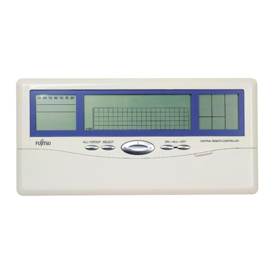
2-3. NAMES AND FUNCTIONS OF THE PARTS TIMER CONTROL OPERATION AREA CENTRAL CONTROL AREA CONTROL AREA Q R S CLOCK MASTER ADJUST CONTROL TIME TEMP . TIMER TIMER MEMORY CENTRAL ENERGY ANTI CONTROL BACK ZONE MODE DELETE OPERATION CONTROL SAVE FREEZE FILTER ON OFF... - Page 11 TIMER CONTROL AREA 1 DAY OF THE WEEK DISPLAY Displays the day of the week. 2 CLOCK AND ADDRESS DISPLAY Shows the current time and address. 3 ALL CLEAR BUTTON To delete all set value in the central remote controller. 4 CLOCK ADJUST BUTTON To set the time.
-
Page 12: Precautions When Setting The System
2-4. PRECAUTIONS WHEN SETTING THE SYSTEM 2-4-1. Priority of remote controller setting The most recent control transmission has priority. In other words, if two controllers (standard re- mote controller, central remote controller) send different control command to one indoor unit, it is the last transmission that will have priority and be used by the indoor unit. -
Page 13: Setting
3. SETTING 3-1. FLOW OF INSTALLATION The following is the flow of the installation of a central remote controller. • INSTALLATION DIP-SW setting • • • • Refer to “INSTALLATION INSTRUCTION SHEET INSTRUCTION SHEET”. Installation / Wiring • • • • Refer to“INSTALLATION INSTRUCTION SHEET”. - Page 14 Notes Setting control panel DIP SW2 Sw state Details Non-display Display For setting filter indicator °C display °F display For setting the unit for the temperature display DIP SW2 Validity Invalidity For validity / invalidity the standard remote controller operation prohibit function Disabled Enabled For enabling / disabling the backup function...
-
Page 15: Setting Operation
Turn on power Initial setting Clock setting Group information store Test operation 3-2. SETTING OPERATION 3-2-1. Turn on power Once the installation and wiring has been completed, use the following procedure to turn on the power. 1. Turn on the power for all connected indoor units. 2. - Page 16 Turn on power Initial setting Clock setting Group information store Test operation Setting of central remote controller address System information scanning Automatic storing Manual storing 1 Manual storing 2 XXXX.XX Version display Note • When in initial setting mode, will light up. •...
- Page 17 Turn on power Initial setting Clock setting Group information store Test operation (1) Central remote controller address setting Use the following procedure to set the central remote controller address. CLOCK MASTER CONTROL ADJUST TIME TEMP . TIMER TIMER MEMORY CENTRAL ENERGY ANTI CONTROL...
- Page 18 Turn on power Initial setting Clock setting Group information store Test operation (2) System information scanning Searches all the indoor units connected by the communication cable and store them in the central remote controller. CLOCK MASTER CONTROL ADJUST TIME TEMP . TIMER TIMER MEMORY...
- Page 19 Turn on power Initial setting Clock setting Group information store Test operation Notes • The system information scanning requires approximately 30 minutes to complete. (The time will depend upon the number of indoor units connected.) • Stop the operation of the indoor unit before performing system information scanning. DELETE •...
- Page 20 Turn on power Initial setting Clock setting Group information store Test operation • System information scanning error An error during the system information scanning will be shown in following manner. System setting error flashing: System setting error Cause of error: System setting has not been properly performed.
- Page 21 Turn on power Initial setting Clock setting Group information store Test operation • Press to move among the errors. • Press to cancel the error display and return to the initial setting menu. BACK • When an error occurs, the number of units with errors will appear in •...
- Page 22 Turn on power Initial setting Clock setting Group information store Test operation Automatic storing CLOCK MASTER ADJUST CONTROL TIME TEMP . TIMER TIMER MEMORY CENTRAL ENERGY ANTI CONTROL BACK ZONE MODE CONTROL FREEZE DELETE OPERATION SAVE FILTER ON OFF TIMER DAY OFF TIMER MEMORY...
- Page 23 Turn on power Initial setting Clock setting Group information store Test operation Manual storing 1 CLOCK MASTER ADJUST CONTROL TIME TEMP . TIMER TIMER MEMORY CENTRAL ENERGY ANTI CONTROL BACK ZONE MODE CONTROL FREEZE DELETE OPERATION SAVE FILTER ON OFF TIMER DAY OFF TIMER...
- Page 24 Turn on power Initial setting Clock setting Group information store Test operation Repeat steps 3 and 4 to continue storing in se- quence. Once all the storing has been completed, press to return to the initial setting menu. Manual storing 2 CLOCK MASTER CONTROL...
- Page 25 Turn on power Initial setting Clock setting Group information store Test operation to select the desired central control number from the 100 segments, press . (The central remote controller will be in a wait mode for a signal from the indoor unit.) •...
-
Page 26: Clock Setting
Turn on power Initial setting Clock setting Group information store Test operation 3-2-3. Clock setting The clock setting can be used to set the current time or set various setting of the central remote controller. CLOCK MASTER CONTROL ADJUST TIME TEMP . - Page 27 Turn on power Initial setting Clock setting Group information store Test operation Press and set the current day. ON OFF Press and set the beep enable / disable set- ting. CLOCK Finally, press to end the clock setting. ADJUST Note If there is an indoor unit that is operating based on the timer of the central remote controller.
-
Page 28: Group Information Store
Turn on power Initial setting Clock setting Group information store Test operation 3-2-4. Group information store It is necessary to do group information store before group control is conducted with the central remote controller. The following shows the procedure of group information store. CLOCK MASTER ADJUST... - Page 29 Turn on power Initial setting Clock setting Group information store Test operation • • • • • To delete the stored information in group GROUP Press to enter the group information store. SETTING to select the group whose stored infor- mation is to be deleted and then press set it.
-
Page 30: Test Operation
Turn on power Initial setting Clock setting Group information store Test operation 3-2-5. Test operation CLOCK MASTER CONTROL ADJUST TIME TEMP . TIMER TIMER MEMORY CENTRAL ENERGY ANTI CONTROL BACK ZONE MODE DELETE OPERATION CONTROL SAVE FREEZE FILTER ON OFF TIMER DAY OFF TIMER... - Page 31 Turn on power Initial setting Clock setting Group information store Test operation Press to send the signal and test operation setting is sent to the indoor unit. will flash as the signal is being transmitted. • 60 minute test operation starts. •...
-
Page 32: Error Display
4. ERROR DISPLAY If the and the number for the central control number flash during operation, there is an error at the relevant remote control group. Start the error monitor, identify the error and remove the cause. CLOCK MASTER ADJUST CONTROL TIME TEMP . - Page 33 TIME Press to select the indoor units in the remote control group selected in 3. TIME Continue pressing , the error codes for the outdoor unit and the central re- mote controller are displayed. Each of the displays is shown below. Indoor unit error display •...
-
Page 34: Error Codes
4-2. ERROR CODES The following explains the meaning of each of the error codes. If outdoor unit error Error If central remote controller If indoor unit error Code error S series V series No error No error No error No error –... -
Page 35: All Clear Switch
4-3. ALL CLEAR SWITCH Press to restart the central remote controller. CLOCK MASTER CONTROL ADJUST TIME TEMP . TIMER TIMER MEMORY CENTRAL ENERGY ANTI CONTROL BACK ZONE MODE DELETE OPERATION CONTROL SAVE FREEZE FILTER ON OFF TIMER DAY OFF TIMER MEMORY GROUP RESET... -
Page 36: Specifications
5. SPECIFICATIONS 5-1. SPECIFICATIONS Operation panel Communication adapter Supply power 50 — 60 Hz 220 — 240 V Power consumption (W) 4.8 W Size (H × W × D mm) 143 × 296 × 22 (107) × 288 × 100 Weight (g) 1300 5-2. - Page 38 P/N9367842018-06...
Need help?
Do you have a question about the UTB-YCA and is the answer not in the manual?
Questions and answers