
Related Manuals for Fujitsu MB95200H/210H Series


Summary of Contents for Fujitsu MB95200H/210H Series
- Page 1 Fujitsu Microelectronics (Shanghai) Co., Ltd. MCU-AN-500009-E-10 Application Note F²MC-8FX FAMILY 8-BIT MICROCONTROLLER MB95200H/210H SERIES HOW TO USE DBG PIN APPLICATION NOTE...
-
Page 2: Revision History
Fujitsu sales representative or Fujitsu authorized distributor. 2. Fujitsu will not be liable for infringement of copyright, industrial property right, or other rights of a third party caused by the use of information or schematic diagrams described in this manual. -
Page 3: Table Of Contents
DBG pin operation V1.0 CONTENTS CONTENTS REVISION HISTORY ......................2 CONTENTS .......................... 3 1 INTRODUCTION......................4 2 FUNCTION OF DBG PIN ....................5 DBG pin hardware connection (debug mode)............5 Performance in debug mode ................... 5 Performance in free-run mode................. 5 3 HOW TO USE DBG PIN.................... -
Page 4: Introduction
DBG pin operation V1.0 Chapter 1 Introduction 1 Introduction This application note describes how to use DBG pin. The DBG pin can be used as 1-line UART communication port in debug mode and can be used as P12/EC0 in free-run mode. MCU-AN-500009-E-10 –... -
Page 5: Function Of Dbg Pin
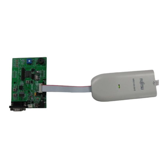
DBG pin operation V1.0 Chapter 2 Function of DBG pin 2 Function of DBG pin This chapter explains functions of DBG pin in different modes. 2.1 DBG pin hardware connection (debug mode) Figure 2-1 DBG Pin Hardware Connection in Debug Mode 2.2 Performance in debug mode DBG pin is used as 1-line UART pin when target MCU enter into debug mode. -
Page 6: How To Use Dbg Pin
DBG pin operation V1.0 Chapter 3 How to Use DBG Pin 3 How to Use DBG Pin This chapter gives some examples for DBG pin setting in different modes. 3.1 Used as 1-line UART pin / P12 pin In Debug mode, DBG pin is used as 1-line UART pin automatically. DBG pin keeps high when UART is in idle status. -
Page 7: Precautions On Using Dbg Pin
DBG pin operation V1.0 Chapter 4 Precautions on using DBG pin 4 Precautions on using DBG pin This chapter describes precautions on using DBG pin. 1. The peripheral circuit connected to DBG pin shouldn’t affect 1-line UART communication when using BGM Adapter for debugging. Please refer to Figure 2-1 when designing user board. -
Page 8: Sample Code
5 Sample code Start.asm //================================================================== // F MC-8L Family SOFTUNE C Compiler sample startup routine, // ALL RIGHTS RESERVED, COPYRIGHT (C) FUJITSU LIMITED 1986 // LICENSED MATERIAL - PROGRAM PROPERTY OF FUJITSU LIMITED //================================================================== //Sample code for initialization //----------------------------------------------------------------------- .PROGRAM start .TITLE... - Page 9 DBG pin operation V1.0 Chapter 5 Sample code ___/ //Begin of actual code section //======================================================== //The Mode Byte is defined at the beginning of the start.asm .SECTION RESVECT, CONST, LOCATE=H'FFFD .DATA.B .DATA.W __start ; code area .SECTION CODE, CODE, ALIGN=1 __start: ;...
- Page 10 DBG pin operation V1.0 Chapter 5 Sample code vector.c /******************************vector.c*********************************/ THIS SAMPLE CODE IS PROVIDED AS IT IS AND IS SUBJECT TO ALTERATIONS. FUJITSU MICROELECTRONICS ACCEPTS NO RESPONSIBILITY OR LIABILITY FOR ANY ERRORS OR INFRINGEMENT FOR ANY PURPOSES. /********************************************************************/ // VECTORS.C Interrupt level (priority) setting...
- Page 11 DBG pin operation V1.0 Chapter 5 Sample code //=================================================================== //extern unsigned int delay_timer; __interrupt void DefaultIRQHandler (void); // Vector definition // Use following statements to define vectors. // All resource related vectors are predefined. // Remaining software interrupts can be added hereas well. #pragma intvect DefaultIRQHandler 0 //IRQ0: external interrupt ch4 #pragma intvect DefaultIRQHandler 1...
- Page 12 DBG pin operation V1.0 Chapter 5 Sample code //set DBG pin as EC0 pin void p12_as_ec0(void) SYSC = 0xE3; // set P12 as EC0 pin, disable HCLK1 T00CR0 = 0x71; // interval timer, external clock source. TMCR0 = 0x43; // 8bit mode, output timer00. T00DR = 0x08;...
Need help?
Do you have a question about the MB95200H/210H Series and is the answer not in the manual?
Questions and answers