Table of Contents
Advertisement
AIR CONDITIONER
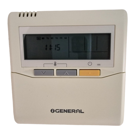
REMOTE CONTROLLER
(WIRED TYPE)
UTY-RNN M
INSTALLATION MANUAL
For authorized service personnel only.
INSTALLATIONSANLEITUNG
Nur für autorisiertes Personal.
MANUEL D'INSTALLATION
Pour le personnel agréé uniquement.
MANUAL DE INSTALACIÓN
Solo para personal autorizado.
MANUALE D'INSTALLAZIONE
Ad uso esclusivo del personale autorizzato.
ΕΓΧΕΙΡΙΔΙΟ ΕΓΚΑΤΑΣΤΑΣΗΣ
Για εξουσιοδοτημένο προσωπικό σέρβις.
MANUAL DE INSTALAÇÃO
Apenas para técnicos autorizados.
РУКОВОДСТВО ПО УСТАНОВКЕ
Для уполномоченного персонала.
MONTAJ KILAVUZU
Yetkili servis personeli içindir.
安裝說明書
只限授權服務人員。
PART NO. 9373328162-04
Advertisement
Table of Contents

Summary of Contents for Fujitsu UTY-RNN*M series
- Page 1 AIR CONDITIONER REMOTE CONTROLLER (WIRED TYPE) UTY-RNN M INSTALLATION MANUAL For authorized service personnel only. INSTALLATIONSANLEITUNG Nur für autorisiertes Personal. MANUEL D'INSTALLATION Pour le personnel agréé uniquement. MANUAL DE INSTALACIÓN Solo para personal autorizado. MANUALE D'INSTALLAZIONE Ad uso esclusivo del personale autorizzato. ΕΓΧΕΙΡΙΔΙΟ...
-
Page 2: Table Of Contents
INSTALLATION MANUAL 2. ACCESSORIES PART NO. 9373328162-04 The following installation parts are supplied. Use them as required. AIR CONDITIONER REMOTE CONTROLLER Name and Shape Q’ty Application (WIRED TYPE) Installation manual This manual Contents 1. SAFETY PRECAUTIONS ..........1 Operating manual Instruction book for operation 2. -
Page 3: Selecting An Installation Location
● Display panel 4. SELECTING AN INSTALLATION 18 19 LOCATION 4.1. Dimensions 23 24 25 26 27 “ ”, “ ” (Set Temperature Button) “ ” (Timer Mode/Clock Adjust Button) “ ” (Day/Day OFF Button) “ ” (Set Back Button) “... -
Page 4: Installing The Remote Controller
5. INSTALLING THE REMOTE Earth (Ground) the remote controller if it has an earth (a ground) cable. CONTROLLER Wrap the connector and remote controller cables with vinyl tape or some other type 5.1. Installation of insulation as shown in the fi gure. Remote controller 5.1.1. -
Page 5: Connection Of Remote Controller Cable
5.3. Connection of Remote Controller Cable Outdoor unit / Remote controller Remote controller power supply cable terminal block terminal block Indoor unit CAUTION • When connecting the remote controller cable to the wall mounted type and the fl oor type indoor unit, do not connect it to the outdoor unit or the indoor unit power terminal block. -
Page 6: Turning On The Power
(2) Remote controller DIP switch 1 setting CAUTION Set the remote controller DIP switch 1-No. 2 according to the following table. When select the “Remote controller setting”, if the Number of remote Master unit Slave unit detected temperature value between the temperature DIP Switch 1-No. - Page 7 (5) Press the TIMER SET button to confi rm the setting. 1) Filter sign Press the TIMER SET button for a few seconds until the setting value The indoor unit has a sign to inform the user that it is time to clean the stops fl...
-
Page 8: Test Operation
7) Heater room temperature correction 13) Setting record Depending on the installed environment, the room temperature sensor Record any changes to the settings in the following table. may require a correction. Setting Description Setting Value The settings may be changed as shown in the table below. Filter sign (♦... -
Page 9: Error Codes
Discharge temp. 11. ERROR CODES ● ● ◊ sensor error Compressor temp. If you use a wired remote controller, error codes will appear on the remote ● ● ◊ controller display. sensor error If you use a wireless remote controller, the lamp on the IR receiver unit will Outdoor unit Heat Ex.


Need help?
Do you have a question about the UTY-RNN*M series and is the answer not in the manual?
Questions and answers
What is the solution if it gives me an Error 84 ?