Advertisement
Quick Links
MS-2113 Radio Installation Quick Guide
This quick guide explains how to install an RC-200 wireless base station, an All Sport radio receiver, or an All
Sport MX-1 Interface Box inside an MS-2113 portable scoreboard. For more information about operation and
maintenance of the MS-2113 scoreboard, refer to the refer to the MS-2113 Portable LED Scoreboard Display
Manual (DD3277683), shipped with the scoreboard and available at www.daktronics.com/manuals.
Before beginning, ensure the scoreboard is powered off/unplugged!
RC-200 Base Station/All Sport Radio Receiver
Both the RC-200 base station and the All Sport Gen VI radio unit have the
same dimensions and connections, so either may be installed the same way.
1. The left-rear side of the scoreboard cabinet has 3 slotted latches securing
the access door. Use a flathead screwdriver to turn all 3 latches 1/2 twist
counterclockwise and carefully open the door.
2. On the left side of the scoreboard cabinet interior is a bracket to hold a
radio unit in place. Route the gray power/signal cable through the bottom
of the bracket, then carefully slide the radio unit down into the bracket.
If it's too tight of a fit, remove the rear hook and loop fastener strips or
use a 5/16" wrench/socket to loosen the nuts on the sides of the bracket.
Ensure the black antenna cable also extends out the bottom of the
bracket. See Figure 1.
3. Use a 5/16" wrench/socket to remove the nut and lock washer from the
antenna connector, then push it through the bottom middle "D" hole in
the scoreboard face sheet so it protrudes out the front.
4. On the front of the scoreboard, reattach the lock washer and nut, then
attach the black radio antenna to the connector, turning the nut on the
antenna until it is snug.
Rotate the antenna so that it is pointing straight upward (it should look like
a capital "L" when viewed from the right side). See Figure 2.
Note: If the scoreboard will be placed where it may be hit by flying
objects, participants, or spectators, attach two U-bolts horizontally
across the radio antenna to protect it.
5. Attached to the rear access door is the driver enclosure. Remove the
metal cover of the driver enclosure by lifting it up, then back and down to
access the scoreboard driver.
6. Connect the 6-pin plug of the gray power/signal cable to the mating 6-pin
J21 jack on the driver. See Figure 3.
7. Put the metal cover back on the driver enclosure, carefully coil up the gray
power/signal cable so it doesn't get pinched in the door, then close the
rear access door and secure the three latches.
8. Power on the scoreboard and control console to verify the radio settings
are correct.
DD4661729
Rev 00
07 April 2020
RC-200 Base Station Settings
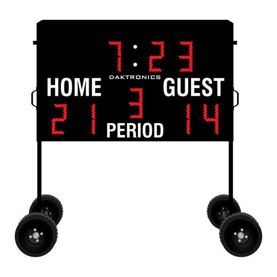
The base station is preset to Function 2, Group 1, Channel 1. When the display is powered on, it will briefly display
the broadcast ("b1") and channel ("C1") numbers in the clock digits (Figure 4). Ensure these numbers match
the settings in the RC-200 handheld controller. If the default settings do not appear to work, refer to the Remote
Control System RC-200 All Sport Operation Manual (DD3572889), available at www.daktronics.com/manuals.
All Sport Radio Receiver Settings
The radio receiver is preset to Broadcast Group 1, Channel 1. When the display is powered on, it will briefly display
the broadcast ("b1") and channel ("C1") numbers in the clock digits (Figure 4). Ensure these numbers match the
settings in the All Sport control console. If the default settings do not appear to work, refer to the Gen VI Radio
Installation Manual (DD2362277), available at www.daktronics.com/manuals.
Note: If there are other All Sport controlled displays in the area operating with radio signal, each display receiver
must be set to a different channel number (typically starting with 1 and numbering consecutively).
RC-200 Radio Settings
CONNECTING VIA
B:1
Figure 1: Radio Unit in Bracket
Figure 2: Radio Antenna
Figure 3: Radio Power/Signal (J21)
201 Daktronics Drive
Brookings, SD 57006-5128
www.daktronics.com/support
800.325.8766
All Sport Radio Settings
RADIO SETTINGS
C:1
BCAST 1
CHAN 01
Page 1 of 2
RC-200
(Broadcast & Channel)
HOME
DAKTRONICS
GUEST
PERIOD
Figure 4: Default Radio Settings
Advertisement

Related Manuals for Daktronics MS-2113


Summary of Contents for Daktronics MS-2113
- Page 1 The base station is preset to Function 2, Group 1, Channel 1. When the display is powered on, it will briefly display maintenance of the MS-2113 scoreboard, refer to the refer to the MS-2113 Portable LED Scoreboard Display the broadcast (“b1”) and channel (“C1”) numbers in the clock digits (Figure 4). Ensure these numbers match Manual (DD3277683), shipped with the scoreboard and available at www.daktronics.com/manuals.
- Page 2 Replace these nuts back on the threaded studs so they do not get lost. There are two main ways to connect an All Sport MX-1 Interface Box to an MS-2113, either internally or externally. 5. Use a Phillips head screwdriver to loosen the two middle screws on top of the scoreboard cabinet. Place the...
Need help?
Do you have a question about the MS-2113 and is the answer not in the manual?
Questions and answers