
Summary of Contents for Dave Embedded Systems Axel ULite
- Page 1 AXEL ULite ARM Cortex A7 MPCore CPU Module Lite Line HARDWARE MANUAL www.dave.eu DAVE Embedded Systems info@dave.eu...
- Page 2 AXEL ULite Hardware Manual v.1.0.2 <Page intentionally left blank> August, 2019 2/65...
-
Page 3: Table Of Contents
AXEL ULite Hardware Manual v.1.0.2 Table of Contents 1 Preface.............................7 1.1 About this manual......................7 1.2 Copyrights/Trademarks.....................7 1.3 Standards..........................7 1.4 Disclaimers........................7 1.5 Warranty..........................7 1.6 Technical Support......................8 1.7 Related documents......................9 1.8 Conventions, Abbreviations, Acronyms................9 2 Introduction..........................11 2.1 Product Highlights......................12 2.2 Block Diagram.........................13 2.3 Feature Summary......................14... - Page 4 AXEL ULite Hardware Manual v.1.0.2 6.2 Variant base peripherals....................40 6.2.1 FULL GPIO configuration ..................40 6.3 HMI configuration – use case 1..................41 6.3.1 LCD controller ......................41 6.3.2 ECSPI2 ........................43 6.3.3 I²C2 ........................43 6.3.4 KPP ........................43 6.3.5 UART1 ........................44 6.3.6 UART2 ........................
- Page 5 10 RESERVED AREA registration....................62 Illustration Index Fig. 1: AXEL ULite........................11 Fig. 2: AXEL ULite block diagram.....................13 Fig. 3: Board layout - top view....................24 Fig. 4: Board bottom - top view....................25 Fig. 5: Simplified block diagram of integrated power supply unit..........53 Fig.
- Page 6 AXEL ULite Hardware Manual v.1.0.2 August, 2019 6/65...
-
Page 7: Preface
DAVE Embedded Systems does not assume any responsibility about availability, supplying and support regarding all the products mentioned in this manual that are not strictly part of the AXEL ULite CPU module. AXEL ULite CPU modules are not designed for use in life support appliances, devices, or systems where malfunction of these products can reasonably be expected to result in personal injury. -
Page 8: Technical Support
AXEL ULite Hardware Manual v.1.0.2 DAVE Embedded Systems will not be responsible for any defects or damages to other products not supplied by DAVE Embedded Systems that are caused by a faulty AXEL ULite module. Technical Support We are committed to making our product easy to use and will help customers use our CPU modules in their systems. -
Page 9: Related Documents
AXEL ULite Hardware Manual v.1.0.2 Related documents Document Location DAVE Developers Wiki http://wiki.dave.eu/index.php/Main_Page Tab. 1: Related documents Conventions, Abbreviations, Acronyms Abbreviation Definition Button EMAC Ethernet Media Access Controller General purpose input GPIO General purpose input and output General purpose output... - Page 10 AXEL ULite Hardware Manual v.1.0.2 Revision History Version Date Notes 0.0.1 June 2016 First draft (PRELIMINARY) 0.9.0 August 2016 First Release 1.0.0 September 2016 Release 1.0.1 December 2018 Minor fixes 1.0.2 August 2019 Minor fixes August, 2019 10/65...
-
Page 11: Introduction
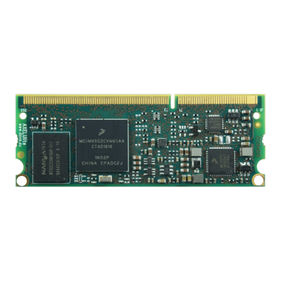
AXEL ULite Hardware Manual v.1.0.2 Introduction AXEL ULite is the brand new solution made by DAVE Embedded Systems, based on the recent NXP/Freescale i.MX6UL Ultra Lite application processor. AXEL ULite defines a new limit in low power consumption with its ARM Cortex A7 architecture and enables customers to design a new concept of Embedded IoT devices. -
Page 12: Product Highlights
AXEL ULite Hardware Manual v.1.0.2 Product Highlights ● ULTRA LOW POWER thanks to ARM Cortex A7 MPCore@528 MHz ● pin to pin compatibility with AXEL LITE SOM based on i.MX6 ● i.MX6 software full compatibility ● High flexibility with up to 4 different scalable CPU versions (Base, General Purpose, Security) ●... -
Page 13: Block Diagram
AXEL ULite Hardware Manual v.1.0.2 Block Diagram Fig. 2: AXEL ULite block diagram August, 2019 13/65... -
Page 14: Feature Summary
AXEL ULite Hardware Manual v.1.0.2 Feature Summary The following table summarizes the features available with AXEL ULite: Feature Specifications Options NXP/Freescale i.MX6 UL ARM Cortex A7 MPCore @ 528 MHz Cache L1: 32 Kbyte instruction, 32 Kbyte data L2: Unified data/instruction, 128 K... -
Page 15: Tab. 5: Electrical, Mechanical And Environmental Specifications
AXEL ULite Hardware Manual v.1.0.2 Feature Specifications Options Dimensions 67,50 mm x 25,40 mm Operating Commercial (0°C / +70°C) Temperature temperature Range range Industrial (-40°C / +85°C) Temperature Range Extended (-40°C / +105°C) Temperature Range Weight 6.4 g Connectors SODIMM 204 pin Tab. -
Page 16: Design Overview
AXEL ULite Hardware Manual v.1.0.2 Design overview The heart of AXEL ULite module is composed by the following components: ● NXP i.MX6 UL core SoC application processor ● Power supply unit with 3V3 single rail or wide 3.7-5.5V input ● DDR memory bank ●... - Page 17 AXEL ULite Hardware Manual v.1.0.2 The i.MX6UL application processor is composed of the following major functional blocks: ● ARM Cortex-A7 MPCore CPU Processor, featuring: ● 128KB unified L2 cache ● NEON MPE co-processor ● External memories interconnect ● Connectivity peripherals, including ●...
-
Page 18: Ddr3 Memory Bank
AXEL ULite Hardware Manual v.1.0.2 DDR3 memory bank DDR3 SDRAM memory bank is composed by 16-bit width chip. The following table reports the SDRAM specifications: Dimension Value CPU connection Multi-mode DDR controller (MMDC) Size min 256 MB Size max 512 GB... -
Page 19: Reliable Storage Strategy
Reliable Storage Strategy Any embedded product requires to be reliable, robust and economic. This is the reason why DAVE Embedded Systems introduced the usage of a good combination of memories that works perfectly in their context and meet all embedded systems goals. NOR and NAND flash are the key components of this strategy. -
Page 20: Write Endurance
AXEL ULite Hardware Manual v.1.0.2 Attribute NAND Read Speed Good Tab. 7: comparison 3.2.1.1 Write endurance The write endurance of SLC floating-gate NOR flash is typically equal to or greater than that of NAND flash, while MLC NOR and NAND flash have similar endurance capabilities. -
Page 21: Nor Flash Bank
NOR flash bank NOR flash is a Serial Peripheral Interface (SPI) device. This device is connected to the eCSPI channel 1. Specific models of the AXEL ULite SOM provide the SPI NOR as boot memory. The following table reports the NOR flash specifications:... -
Page 22: Nand Flash Bank
For detailed information, please refer to chapter 2 “Memory Maps” of the i.MX Applications Processor Reference Manual. Power supply unit AXEL ULite, as the other LITE Line CPU modules, embeds all the elements required for powering the unit, therefore power sequencing is self-contained and simplified. Nevertheless, power must be provided from carrier board, and therefore users should be aware of the ranges power supply can assume as well as all other parameters. -
Page 23: Power Consumption
This section will be completed in a future version of this manual. CPU module connectors All interface signals AXEL ULite provides are routed through SODIMM DDR3 204 pin (named J2). The dedicated carrier board must mount the mating connector and connect the desired peripheral interfaces according to AXEL ULite pinout specifications. -
Page 24: Mechanical Specifications
This chapter describes the mechanical characteristics of the AXEL ULite SOM. Mechanical drawings are available in DXF format on request. Board Layout The following figures shows the physical dimensions of the AXEL ULite module. Fig. 3: Board layout - top view August, 2019... -
Page 25: Connectors
AXEL ULite Hardware Manual v.1.0.2 Connectors The following figure shows the AXEL ULite connectors layout: Fig. 4: Board bottom - top view The following table reports connectors specifications: Part number Standard SO-DIMM 204-pin (DDR3) Mating DDR3 SO-DIMM SOCKET connectors Part number : TE Connectivity 2013289-1... -
Page 26: Mechanical Data Table
AXEL ULite Hardware Manual v.1.0.2 Mechanical data table All dimensions on the following table are in millimeters. Dimension Value Width 67.60 mm Depth 25.40 mm Max components' height – top side 1.35 mm Max components' height – bottom side 1.2 mm PCB height 1.086 +-10... -
Page 27: Pinout Table
AXEL ULite Hardware Manual v.1.0.2 Pinout table This chapter contains the pinout description of the AXEL ULite module, grouped in two tables (odd and even pins) that report the pin mapping of the 204-pin SO-DIMM AXEL ULite connector. Each row in the pinout tables contains the following information:... - Page 28 AXEL ULite Hardware Manual v.1.0.2 J2.21 ETH_TX_M LAN.TXM J2.23 ETH_RX_P LAN.RXP J2.25 ETH_RX_M LAN.RXM J2.27 SNVS_TAMPER0 CPU.SNVS_TAMPER0 J2.29 SNVS_TAMPER1 CPU.SNVS_TAMPER1 Internally connected to ethernet PHY INT J2.31 SNVS_TAMPER2 CPU.SNVS_TAMPER2 signal J2.33 SNVS_TAMPER3 CPU.SNVS_TAMPER3 J2.35 DGND DGND J2.37 SNVS_TAMPER4 CPU.SNVS_TAMPER4 J2.39 CSI_HSYNC CPU.CSI_HSYNC...
- Page 29 AXEL ULite Hardware Manual v.1.0.2 J2.99 ENET2_RX_EN CPU.ENET2_RX_EN J2.101 ENET2_TX_CLK CPU.ENET2_TX_CLK J2.103 ENET2_RX_ER CPU.ENET2_RX_ER J2.105 ENET2_TX_EN CPU.ENET2_TX_EN J2.107 ENET2_TX_DATA1 CPU.ENET2_TX_DATA1 A16 J2.109 DGND DGND Not connected. Leave J2.111 N.C. this pin floating. Not connected. Leave J2.113 N.C. this pin floating.
- Page 30 AXEL ULite Hardware Manual v.1.0.2 Internally connected to PMIC (used as I2C1 J2.149 UART4_RX_DATA CPU.UART4_RX_DATA G16 SDA) Internally connected to PMIC (used as I2C1 J2.151 UART4_TX_DATA CPU.UART4_TX_DATA SCL) J2.153 DGND DGND Not connected. Leave J2.155 N.C. this pin floating. Not connected. Leave J2.157 N.C.
-
Page 31: Tab. 13: J2 Odd Pins (1 To 203)
AXEL ULite Hardware Manual v.1.0.2 Tab. 13: J2 odd pins (1 to 203) August, 2019 31/65... - Page 32 AXEL ULite Hardware Manual v.1.0.2 J2 even pins (2 to 204) Ball/ Pin Name Internal Connections Notes J2.2 DGND DGND J2.4 3.3VIN INPUT VOLTAGE J2.6 3.3VIN INPUT VOLTAGE J2.8 3.3VIN INPUT VOLTAGE J2.10 3.3VIN INPUT VOLTAGE J2.12 DGND DGND J2.14 PMIC_LICELL PMIC.LICELL...
- Page 33 AXEL ULite Hardware Manual v.1.0.2 J2.56 DGND DGND J2.58 GPIO1_IO09 CPU.GPIO_IO09 Not connected. Leave J2.60 N.C. this pin floating. Internally connected to 240 ohm pull-up to J2.62 JTAG_VREF CPU.JTAG_VREF Internally connected to J2.64 JTAG_MOD CPU.JTAG_MOD 10K pull-down J2.66 JTAG_TDI CPU.JTAG_TDI J2.68...
- Page 34 AXEL ULite Hardware Manual v.1.0.2 NAND flash Internally connected to J2.112 NAND_DATA04 CPU.NAND_DATA04 NAND flash Internally connected to J2.114 NAND_DATA05 CPU.NAND_DATA05 NAND flash Internally connected to J2.116 NAND_DATA06 CPU.NAND_DATA06 NAND flash Internally connected to J2.118 NAND_DATA07 CPU.NAND_DATA07 NAND flash J2.120 MEM_Wpn MEM_Wpn J2.122 DGND...
-
Page 35: Tab. 14: J2 Even Pins (2 To 204)
AXEL ULite Hardware Manual v.1.0.2 J2.182 LCD_DATA22 CPU.LCD_DATA22 J2.184 LCD_DATA23 CPU.LCD_DATA23 J2.186 USB_OTG2_VBUS CPU.USB_OTG2_VBUS U12 J2.188 USB_OTG1_VBUS CPU.USB_OTG1_VBUS T12 J2.190 DGND DGND Not connected. Leave J2.192 N.C. this pin floating. J2.194 USB_OTG1_CHD# CPU.USB_OTG1_CHD J2.196 USB_OTG2_DN CPU.USB_OTG2_DN J2.198 USB_OTG2_DP CPU.USB_OTG2_DP J2.200 USB_OTG1_DP CPU.USB_OTG1_DP... -
Page 36: Peripheral Interfaces
AXEL ULite modules implement a number of peripheral interfaces through the SO-DIMM connector. Some interfaces/signals are available only with/without certain configuration options of the AXEL ULite module. The signals for each interface are described in the related tables. The following notes summarize the column headers for these tables: ●... -
Page 37: Fixed Hw Peripherals
AXEL ULite Hardware Manual v.1.0.2 Fixed HW peripherals Fixed HW peripherals are the devices connected on dedicated pins and are not to multiplexing and can not be multiplexed for other functionalities In the sections below you can find the different standard devices within their system configuration 6.1.1... -
Page 38: Usb
AXEL ULite Hardware Manual v.1.0.2 6.1.2 AXEL ULite provides two USB 2.0 On-The-Go (OTG) ports with integrated PHY. Please note that the OTG_ID (USB mode host or device identifier) and the other power related signal as OTG_PWR (power) and OTG_OC (overcurrent) are multiplexed as alternate functions on different balls/connector pins. -
Page 39: Mmc/Sd/Sdio
(FLEXCAN1, FLEXCAN2, SAI1, USB power controls pins) 6.1.4 AXEL ULite provides up to four SPI ports connected to the i.MX6 integrated Enhanced Configurable SPI (ECSPI) controller, featuring: ● Full-duplex synchronous serial interface ●... - Page 40 AXEL ULite Hardware Manual v.1.0.2 transfers ● 32-bit wide by 64-entry FIFO for both transmit and receive data ● Configurable Polarity and phase of the Chip Select (SS) and SPI Clock (SCLK) ● Direct Memory Access (DMA) support August, 2019...
-
Page 41: Ecspi1
AXEL ULite Hardware Manual v.1.0.2 6.1.5 ECSPI1 AXEL ULite on-board bootable SPI Flash is interfaced with the i.MX6UL through the eCSPI1 port on chip select 0. For further details, please refer to Section 3.3. The following table describes the interface signals:... -
Page 42: Variant Base Peripherals
AXEL ULite Hardware Manual v.1.0.2 Pin Name Internal Connections Ball/pin # NAND_DATA04 J2.112 CPU.NAND_DATA04 NAND_DATA05 J2.114 CPU.NAND_DATA05 NAND_DATA06 J2.116 CPU.NAND_DATA06 NAND_DATA07 J2.118 CPU.NAND_DATA07 Variant base peripherals 6.2.1 FULL GPIO configuration The i.MX6UL GPIO module provides general-purpose pins that can be configured as either inputs or outputs, for connections to external devices. -
Page 43: Lcd Controller
AXEL ULite Hardware Manual v.1.0.2 HMI configuration – use case 1 The following scenario shows a possible example of an HMI appliance where the User Interface is the most important functionality. The LCD controller and the touchscreen controller are the main interfaces used for the HMI interaction. - Page 44 AXEL ULite Hardware Manual v.1.0.2 Pin Name Internal Connections Ball/pin # LCD_HSYNC J2.130 CPU.LCD_HSYNC LCD_CLK J2.132 CPU.LCD_CLK LCD_DATA00 J2.134 CPU.LCD_DATA00 LCD_DATA01 J2.136 CPU.LCD_DATA01 LCD_DATA02 J2.138 CPU.LCD_DATA02 LCD_DATA03 J2.140 CPU.LCD_DATA03 LCD_DATA04 J2.142 CPU.LCD_DATA04 LCD_DATA05 J2.144 CPU.LCD_DATA05 LCD_DATA06 J2.148 CPU.LCD_DATA06 LCD_DATA07 J2.150 CPU.LCD_DATA07...
-
Page 45: Ecspi2
AXEL ULite Hardware Manual v.1.0.2 6.3.2 ECSPI2 Pin Name Internal Connections Ball/pin # ECSPI2_SCLK J2.74 CPU.CSI_DATA00 ECSPI2_MOSI J2.76 CPU.CSI_DATA03 ECSPI2_MISO J2.78 CPU.CSI_DATA02 ECSPI2_CS0 J2.80 CPU.CSI_DATA01 6.3.3 I²C2 The following table describes the interface signals: Pin Name Internal Connections Ball/pin # I2C2_SCL J2.38... -
Page 46: Uart1
AXEL ULite Hardware Manual v.1.0.2 6.3.5 UART1 Pin Name Internal Connections Ball/pin # UART1_TX_DATA J2.187 CPU.UART1_TX_DATA UART1_RX_DATA J2.189 CPU.UART1_RX_DATA 6.3.6 UART2 Pin Name Internal Connections Ball/pin # UART2_TX_DATA J2.42 CPU.UART2_TX_DATA UART2_RX_DATA J2.44 CPU.UART2_RX_DATA UART2_RTS J2.179 CPU.UART2_RTS UART2_CTS J2.181 CPU.UART2_CTS 6.3.7... -
Page 47: Iot Gateway - Use Case 2
AXEL ULite Hardware Manual v.1.0.2 IoT Gateway – use case 2 The following scenario shows a possible example of a blind appliance where Connectivity is the most important functionality. The two ethernet controllers, two USB ports, eight UARTs, two I2C, two SPI and one audio peripherals can be used simultaneously into the Gateway pinmuxing application. -
Page 48: Enet2
AXEL ULite Hardware Manual v.1.0.2 6.4.1 ENET2 The second ethernet interface requires an external PHY on the Carrier board. Pin Name Internal Connections Ball/pin # ENET2_RX_DATA1 J2.93 CPU.ENET_RDATA1 ENET2_RX_DATA0 J2.95 CPU.ENET_RDATA0 ENET2_TX_DATA0 J2.97 CPU.ENET_TDATA0 ENET2_RX_EN J2.99 CPU.ENET_RXEN ENET2_TX_CLK J2.101 CPU.ENET_TX_CLK ENET2_RX_ER J2.103... -
Page 49: Uart3 - Four Wires
AXEL ULite Hardware Manual v.1.0.2 6.4.4 UART3 – four wires Pin Name Internal Connections Ball/pin # UART3_TX_DATA J2.191 CPU.UART3_TX_DATA UART3_RX_DATA J2.193 CPU.UART3_RX_DATA UART3_CTS J2.195 CPU.UART3_CTS UART3_RTS J2.197 CPU.UART3_RTS 6.4.5 UART4 – for wires Pin Name Internal Connections Ball/pin # UART4_RX_DATA J2.124... -
Page 50: Uart 7
AXEL ULite Hardware Manual v.1.0.2 6.4.8 UART 7 Pin Name Internal Connections Ball/pin # UART7_TX_DATA J2.170 CPU.LCD_DATA16 UART7_RX_DATA J2.172 CPU.LCD_DATA17 6.4.9 UART 8 – for wires Pin Name Internal Connections Ball/pin # UART8_TX_DATA J2.178 CPU.LCD_DATA20 UART8_RX_DATA J2.180 CPU.LCD_DATA21 UART8_CTS J2.142 CPU.UART8_CTS... -
Page 51: Ecspi3
AXEL ULite Hardware Manual v.1.0.2 Pin Name Internal Connections Ball/pin # ECSPI2_MOSI J2.76 CPU.CSI_DATA03 ECSPI2_MISO J2.78 CPU.CSI_DATA02 ECSPI2_CS0 J2.80 CPU.CSI_DATA01 6.4.13 ECSPI3 Pin Name Internal Connections Ball/pin # ECSPI3_CS0 J2.84 CPU.NAND_READY# ECSPI3_MISO J2.86 CPU.NAND_CLE ECSPI3_SCLK J2.96 CPU.NAND_CS0# ECSPI3_MOSI J2.98 CPU.NAND_CS1# 6.4.14... -
Page 52: Customized Pin Muxing Configuration
AXEL ULite Hardware Manual v.1.0.2 Customized pin muxing configuration Customers can require any other multiplexing contacting the DAVE Embedded Systems' sales department at sales@dave.eu Please contact your sales representative for assistance on pin multiplexing design. Additionally, for Evaluation Kit owners is available on the DAVE... -
Page 53: Power, Reset And Control
AXEL ULite Hardware Manual v.1.0.2 Power, reset and control AXEL ULite system-on-module (SOM for short) is powered by carrier board via VIN_SOM rail. About voltage range, three supported configurations are available. These configurations are indicated by the value of the f field of the ordering code. -
Page 54: Power Supply Unit (Psu) And Recommended Power-Up Sequence
Implementing correct power-up sequence for i.MX6UL processors is not a trivial task because several power rails are involved. AXEL ULite SOM simplifies this task by embedding all the needed circuitry. The following picture shows a simplified block diagram of PSU/voltage monitoring... - Page 55 AXEL ULite Hardware Manual v.1.0.2 Fig. 5: Simplified block diagram of integrated power supply unit The PSU is composed of two main blocks: ● power management integrated circuit (PMIC, NXP PF0100E0 - on request this part is available in automotive grade) ●...
-
Page 56: Power-Up Sequence
AXEL ULite Hardware Manual v.1.0.2 7.1.1 Power-up sequence The typical power-up sequence is the following: 1. (optional) PMIC_LICELL is powered by a Lithium coin cell battery ● I.MX6 UL SNVS domain is powered (VDD_SNVS_IN) 2. VIN_SOM main power supply rail is powered ●... -
Page 57: Reset Scheme And Control Signals
AXEL ULite Hardware Manual v.1.0.2 Reset scheme and control signals The following picture shows the simplified block diagram of reset scheme and voltage monitoring. Fig. 6: Simplified block diagram of reset circuitry and voltage monitoring The available reset signals are described in detail in the following sections. -
Page 58: System Boot
SOM. These two needs - ease of use and configurability - clearly push in opposite directions. During the inception of the AXEL ULite product, specific attention has been addressed to find a viable trade off to satisfy such requirements. -
Page 59: Nand / Sd Option
U-Boot feature, the user will need, sooner or later, to recover (bare-metal restore) the AXEL ULite SOM without using the bootloader itself. The following paragraphs introduce the available options. For further information, please refer to DAVE Embedded Systems Developers Wiki or contact the Technical Support Team. -
Page 60: Sd/Mmc Recovery
AXEL ULite Hardware Manual v.1.0.2 Please refer to the XUELK Quick Start Guide for further details. 7.5.3 SD/MMC Recovery MMC recovery is a valuable options that requires no special hardware at all, apart a properly formatted MMC. When SD/MMC boot option is selected, bootrom looks for a valid bootloader on SD/MMC. -
Page 61: Operational Characteristics
Providing theoretical maximum power consumption value would be useless for the majority of system designers building their application upon AXEL ULite module because, in most cases, this would lead to an over-sized power supply unit. Several configurations have been tested in order to provide figures that are measured on real-world use cases instead. -
Page 62: Configuration1
AXEL ULite Hardware Manual v.1.0.2 supply unit and to implement thermal management properly. 8.2.1 Configuration1 This section will be completed in a future version of this manual. Heat Dissipation This section will be completed in a future version of this manual. -
Page 63: Application Notes
AXEL ULite Hardware Manual v.1.0.2 Application Notes Please refer to the following documents available on DAVE Embedded Systems Developers Wiki: Document Location Tab. 22: Application Notes August, 2019 63/65... -
Page 64: Reserved Area Registration
AXEL ULite Hardware Manual v.1.0.2 RESERVED AREA registration Additional development kit contents, binary images and documentation can be downloaded from the RESERVED AREA of the DAVE Embedded Systems' website. Registering the development kit is required to get access to the RESERVED AREA. The procedure is the following: ●... - Page 65 AXEL ULite Hardware Manual v.1.0.2 Fig. 7: Accessing the RESERVED AREA August, 2019 65/65...
Need help?
Do you have a question about the Axel ULite and is the answer not in the manual?
Questions and answers