Advertisement
Table of Contents
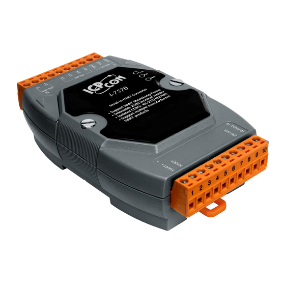
I-7570
Serial to HART Converter
Quick Start Guide
Product Website:
https://www.icpdas-usa.com/i_7570.html
1. Introduction
This quick start manual will guide users to implement the I-7570 module into their
applications in a quick and easy way. For the more detailed information, please refer to
the user's manual in the Fieldbus_CD of ICP DAS ("CD:\hart\convert\i-7570\manual\i-
7570_usermanual.pdf") for detail.
We will use an I-7570 module (as a HART master), one HART slave and one PC as the
example shown in Figure 1-1 and demonstrate how to use the I-7570 utility for I-module
configuration and HART communication test.
I-7570 Serial to HART Converter - QuickStart (Dec/2019)
ICP DAS USA, Inc. |
www.icpdas-usa.com
| 1-310-517-9888 | 24309 Narbonne Ave. Suite 200. Lomita, CA 90717
1
Advertisement
Table of Contents

Related Manuals for ICP DAS USA I-7570


Summary of Contents for ICP DAS USA I-7570
- Page 1 Fieldbus_CD of ICP DAS (“CD:\hart\convert\i-7570\manual\i- 7570_usermanual.pdf”) for detail. We will use an I-7570 module (as a HART master), one HART slave and one PC as the example shown in Figure 1-1 and demonstrate how to use the I-7570 utility for I-module configuration and HART communication test.
- Page 2 [ Step2: Check the LED Indication I-7570 ] Check the PWR LED of I-7570 if it is always on. If yes, it means I7570 is working in the “Firmware Operation” mode. [ Step3: Enable or Disable the Terminator Resistor ] There is a Jumper (JP4) at the I-7570 module, shown in Figure 2-1.
- Page 3 3. Using I-7570 Utility Step1: Turn on the power of I-7570, if the PWR LED of the I-7570 is always on, then it means the I-7570 converter is working in the “Firmware Operation” mode. Step2: Run the “I-7570 Utility”, HC_Tool, and click the “Settings” item like Figure 3-1 to configure the serial connection and HART command parameters.
- Page 4 Step3: Set the “Port Name” and “Auto Configure“ parameters like Figure 3-2. I-7570 Serial to HART Converter - QuickStart (Dec/2019) ICP DAS USA, Inc. | www.icpdas-usa.com | 1-310-517-9888 | 24309 Narbonne Ave. Suite 200. Lomita, CA 90717...
- Page 5 I-7570 Serial to HART Converter - QuickStart (Dec/2019) ICP DAS USA, Inc. | www.icpdas-usa.com | 1-310-517-9888 | 24309 Narbonne Ave. Suite 200. Lomita, CA 90717...
Need help?
Do you have a question about the I-7570 and is the answer not in the manual?
Questions and answers