
Related Manuals for Snorkel S3006P


Summary of Contents for Snorkel S3006P
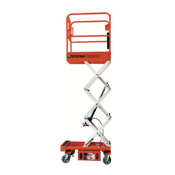
- Page 1 OPERATORS MANUAL S3006P sn: 01-000500+ / 01-****00059+ Part Number 514690-000-EN S3008P sn: 01-000800+ / 01-****00231+ January 2020 S3010P sn: 01-000500+ / 01-****00559+ Original Instructions S3210P sn: 01-000000+ / 01-****00001+...
-
Page 3: Table Of Contents
Platform Raise/Lower Buttons ......9 Daily Preventative Maintenance Checklist ....17 Battery Charger Mode Selector ......9 Preventative Maintenance Report ......17 Upper Controls ............9 General Specifications – S3006P ......18 Emergency Stop Button ........9 General Specifications – S3008P ......19 Interlock Button ...........9 General Specifications – S3010P ......20 Platform Raise/Lower Buttons ......9... -
Page 4: Declaration Of Conformity
DECLARATION OF CONFORMITY This declaration is issued under the sole responsibility of the manufacturer Manufacturer’s Name and Full Address Snorkel Europe Ltd Vigo Centre, Birtley Road, Washington, Tyne & Wear, NE38 9DA, UK Description and Identification of the Machinery Product Description... -
Page 5: Harness Attachment Point
Harness attachment points are provided in the platform and the manufacturer recommends the usage of a fall restraint harness, especially where required by national safety regulations. All harness attachment points on SNORKEL vehicles have been tested with a force of 3,650 lbs (16.3 KN) per person. -
Page 6: Safety Rules
NEVER charge batteries near sparks or open flame. Charging batteries emit explosive hydrogen gas. Modifications to the aerial work platform are prohibited or permissible only at the approval by Snorkel. AFTER USE, secure the work platform from unauthorized use by turning the keyswitch off and removing key. - Page 7 PUSH PRO -0120843...
-
Page 8: Introduction
Introduction When contacting Pop Up for service or parts information, be sure to include the MODEL and SERIAL NUMBERS This manual covers the S3006P, S3008P, S3010P and from the equipment nameplate. Should the nameplate S3210P Aerial Work Platforms. be missing, the SERIAL NUMBER is also stamped on This manual must be stored on the machine at all the front of the chassis. -
Page 9: Special Limitations
Table of Contents Special Limitations Position the machine on a level surface when the lift level sensor alarm sounds. When the machine is prop- Elevating the platform is limited to firm, level surfaces erly positioned on a level surface, the alarm will not only. -
Page 10: Controls And Indicators
Controls and Indicators Controls and Indicators sure all personnel stand clear while operating the aerial platform. The operator shall know the location of each control and indicator and have a thorough knowledge of the • Controls to position the platform are located on function and operation of each before attempting to the lower control panel on the chassis and on the operate the machine. -
Page 11: Ground Operation Button
Controls and Indicators Ground Operation Button Emergency Stop Button The ground operation button prevents platform The emergency stop is a two-position, red push button movement if the platform raise or lower button is on the right side of the upper control panel. accidentally pressed. -
Page 12: Pre-Operation Safety Inspection
Pre-Operation Safety Inspection Pre-Operation Safety Inspection Note Carefully read, understand and follow all safety rules, operating instructions, labels and National Safety Instructions/Requirements. 1. Open the tray and inspect for damage, fluid leaks or missing parts daily. 2. Check daily the level of the hydraulic fluid with the platform fully lowered. -
Page 13: System Function Inspection
System Function Inspection System Function Inspection 6. Test the emergency lowering system for proper operation. Refer to “Controls and Indicators” on page 6 for the locations of various controls and indicators. Push the Lower Control Emergency Stop Button to check for proper operation. All machine functions should be disabled. -
Page 14: Operation
Operation Operation 2. Close and latch the component tray. The aerial platform may be operated from either the 3. Position the machine in the work place and make lower or upper controls. certain the area is flat and horizontal. 4. Step down on each of the brake levers to lock the Danger rear wheels in position. -
Page 15: Platform
Operation Component Tray 1. From the lower controls, pull the emergency stop button outward (refer to Figure 2). Batteries and hydraulic components are enclosed in the component tray on the left side of the chassis. Insert the key into the control selector switch and turn the switch to the upper controls position. -
Page 16: Transporting The Machine
Transporting the Machine Transporting the Machine Lifting With a Tail Lift Use the following procedure to lift the aerial platform Preparing for Transportation with a forklift. Use the following procedure to prepare the aerial plat- form for transportation. Properly stow the aerial platform. 1. -
Page 17: Maintenance
Maintenance Maintenance Check Hydraulic Fluid Make sure that the platform is fully lowered. Warning 2. Visually check to make sure the fluid is within Always block the elevating assembly whenever 6 mm (¼″) of the top of the fill hole. it is necessary to perform maintenance while the 3. -
Page 18: Inspection And Maintenance Schedule
Inspection and Maintenance Schedule Keep the charger dry. 11. Tightly replace the caps on the battery and close and latch the component tray. 1. At the lower controls, turn the control selector switch to the off position. Inspection and Maintenance Schedule 2. -
Page 19: Daily Preventative Maintenance Checklist
Daily Preventative Maintenance Checklist Daily Preventative Maintenance Checklist Preventative Maintenance Report Date: ____________________________________ Serial No: _________________________________ Owner: ___________________________________ Serviced By: ______________________________ Model No: ________________________________ Item Inspect For Operator’s Manual In manual holder, all pages readable and intact Electrical System Battery terminals Clean, connectors tight Battery charge indicator Proper operation... -
Page 20: General Specifications - S3006P
Specifications General Specifications – S3006P Electrical System Aerial Platform Voltage 12 V DC negative chassis ground Working height 3.96 m Source One - 12 V 105 amp hour battery Maximum platform height 1.96 m Fluid recommended distilled water Wheelbase Charger... -
Page 21: General Specifications - S3008P
Specifications General Specifications – S3008P Electrical System Aerial Platform Voltage 12 V DC negative chassis ground Working height 4.56 m Source One - 12 V 105 amp hour battery Maximum platform height 2.56 m Fluid recommended distilled water Wheelbase Charger 15 amp Ground clearance 1.9 cm... -
Page 22: General Specifications - S3010P
Specifications General Specifications – S3010P Electrical System Aerial Platform Voltage 12 V DC negative chassis ground Working height Source One - 12 V 105 amp hour battery Maximum platform height 3.0 m Fluid recommended distilled water Wheelbase Charger 15 amp Ground clearance 1.9 cm Maximum wheel load... -
Page 23: General Specifications - S3210P
Specifications General Specifications – S3210P Electrical System Aerial Platform Voltage 12 V DC negative chassis ground Working height Source One - 12 V 105 amp hour battery Maximum platform height 3.0 m Fluid recommended distilled water Wheelbase Charger 15 amp Ground clearance 1.9 cm Maximum wheel load... - Page 24 Manufacturer’s Address Snorkel Europe Ltd Vigo Centre, Birtley Road, Washington, Tyne & Wear, NE38 9DA, UK PUSH PRO -0120843...
- Page 25 Local Distributor / Lokaler Vertiebshändler / Distributeur local El Distribuidor local / ll Distributore locale EUROPE, MIDDLE EAST AFRICA & ASIA PHONE: +44 (0) 845 1550 057 FAX: +44 (0) 845 1557 756 NORTH & SOUTH AMERICA PHONE: +1 785 989 3000 TOLL FREE: +1 800 225 0317 FAX: +1 785 989 3070 AUSTRALIA...
Need help?
Do you have a question about the S3006P and is the answer not in the manual?
Questions and answers