Baxi POWER HT+ 1.50 User Manual
Hide thumbs
Also See for POWER HT+ 1.50:
- Installation and service manual (117 pages) ,
- User manual (44 pages) ,
- Installation and service manual (124 pages)
Table of Contents
Advertisement
Quick Links
Advertisement
Table of Contents

Related Manuals for Baxi POWER HT+ 1.50


Summary of Contents for Baxi POWER HT+ 1.50
- Page 1 User Guide POWER HT+ 1.50 POWER HT+ 1.70 POWER HT+ 1.90 POWER HT+ 1.110...
- Page 2 Dear Customer, Thank you very much for buying this appliance. Please read through the manual carefully before using the product, and keep it in a safe place for later reference. In order to ensure continued safe and efficient operation we recommend that the product is serviced regularly. Our service and customer service organisation can assist with this.
-
Page 3: Table Of Contents
Contents Contents Safety ................... . 5 General safety instructions . - Page 4 Contents Environmental ..................30 Energy savings .
-
Page 5: Safety
1 Safety Safety General safety instructions For the installer and end user: Danger This appliance is not intended for use by persons (including children) with reduced physical, sensory or mental capabilities, or lack of experience and knowledge, unless they have been given supervision or instruction concerning use of the appliance by a person responsible for their safety. - Page 6 1 Safety Danger If you smell gas: 1. Do not use a naked flame, do not smoke, do not operate electrical contacts or switches (doorbell, light, motor, lift, etc.). 2. Shut off the gas supply. 3. Open the windows. 4. Locate the probable leak and seal it immediately.
-
Page 7: Recommendations
1 Safety Danger Do not spray aerosol near this appliance when it is operating. Danger Do not use or store flammable materials in or near this appliance. Danger Do not place anything against or on this appliance. Danger Do not modify this appliance. Danger Only qualified professionals are authorised to perform maintenance operations. - Page 8 1 Safety Caution Power the appliance via a circuit that includes an omni-polar switch with contact opening distance of 3 mm or more. Caution Have the boiler and heating system drained by a qualified professional if the home is left empty for a long period of time and there is a chance of frost.
-
Page 9: Liabilities
1 Safety Important Never remove or cover labels and data plates affixed to the boiler. Labels and data plates must be legible throughout the entire lifetime of the boiler. Immediately replace damaged or illegible instructions and warning labels. Important Keep this document close to the place where the appliance is installed. -
Page 10: Manufacturer's Liability
1 Safety 1.3.3 Manufacturer's liability Our products are manufactured in compliance with the requirements of the various Directives applicable. They are therefore delivered with the marking and any documents necessary. In the interests of the quality of our products, we strive constantly to improve them. We therefore reserve the right to modify the specifications given in this document. -
Page 11: About This Manual
2 About this manual About this manual General This manual is intended for the end user of a POWER HT + boiler. Symbols used 2.2.1 Symbols used in the manual This manual uses various danger levels to draw attention to special instructions. -
Page 12: Technical Specifications
3 Technical specifications Technical specifications Homologations 3.1.1 Ecodesign Directive This product conforms to the requirements of European Directive 2009/125/EC on the ecodesign of energy-related products. 3.1.2 Certifications We hereby certify that the series of appliances specified below complies with the standard model described in the CE declaration of conformity. AGA certification 7023 G NOx class... -
Page 13: Other Technical Parameters
3 Technical specifications Tab.2 Characteristics of the heating circuit POWER HT+ POWER HT+ POWER HT+ POWER HT+ Unit 1.50 1.70 1.90 1.110 Water content (excluding expansion vessel) litre 2.81 4.98 8.34 9.83 Minimum operating pressure MPa (bar) 0.05 (0.5) 0.05 (0.5) 0.05 (0.5) 0.05 (0.5) Maximum operating pressure (MOP) - Page 14 3 Technical specifications Product name POWER HT POWER HT POWER HT POWER HT + 1.50 + 1.70 + 1.90 + 1.110 Useful heat output at rated heat output 45.0 65.0 85.0 102.0 and high temperature regime Useful heat output at 30% of rated heat 15.0 21.7 28.3...
-
Page 15: Description Of The Product
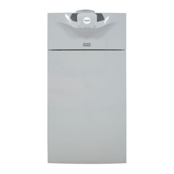
High efficiency heating Electronic control panel Perfectly suitable for cascade systems with several boilers. Main boiler components Fig.2 POWER HT+ 1.50 and POWER HT 1 Control panel + 1.70 2 Flue gas measuring point 3 Flue gas connection 4 On/Off button Fig.3... - Page 16 4 Description of the product Tab.7 Description of the symbols Type of information Symbol Description Information Room temperature (°C) Outdoor temperature (°C) Temperature and hydraulic pressure units: international system or imperial system. °C, °F, bar, PSI Data transmission: only when the wireless remote control is connected. Solar integration available Operating modes Comfort operating mode: comfort room temperature...
-
Page 17: Operation
5 Operation Operation Use of the control panel 5.1.1 Modifying the user parameters Fig.6 1. Press the key to access the parameters. MENU Important Press the key to return to the main display. MENU The user parameters can now be accessed. Use the button to select and modify them. - Page 18 5 Operation 5. Confirm the selection by pressing the button. symbol is displayed. Important When the operating mode Off is activated: The electrical circuits continue to be powered up. The frost protection function is activated. POWER HT + 7609475 - v09 - 22072020...
-
Page 19: Settings
6 Settings Settings List of parameters 6.1.1 Shortcuts menu Tab.8 Functions accessible with the shortcut key Parameter Description Adjustment range Standby/operation Boiler standby/Start-up. Standby : Boiler put on standby. The symbol is displayed. The boiler's operating modes are deactivated. The frost protection function is activated. On : Putting the boiler into operation 316:Hot water boost Forcing domestic hot water pro... -
Page 20: List Of User Parameters
6 Settings Information Description Unit Minimum outside temperature value memorised °C Outside temp min Important The outside sensor must be connected. Maximum outside temperature value memorised °C Outside temp max Important The outside sensor must be connected. Hot water temp 1 Domestic hot water temperature °C Important... - Page 21 6 Settings Tab.13 Time program menu Parameter number Parameter Description Heating circuit Heating circuit 2 Heating circuit 3 Selecting the days or group of days for the timer pro Select days gram. Mon-Sun Selecting a default timer program. 1st Time ON Start of timer period 1.
-
Page 22: Setting The Parameters
6 Settings Tab.16 Temps / mode CH1 – Temps / mode CH2 – Temps / mode CH3 menu Parameter number Parameter Description Factory setting Heating Heating Heating cir circuit 1 circuit 2 cuit 3 1000 1300 The control unit is installed on the boiler: Off : heating is deactivated. -
Page 23: Selecting The Language
6 Settings 6.2.2 Selecting the language Fig.9 1. Press the key to access the parameters. MENU 2. Select the Operator section menu by turning the button. 3. Confirm the menu selection by pressing the button. The Change Language parameter appears. 4. -
Page 24: Setting The Room Temperature Set Point (On Mode)
6 Settings 3. Press the button to start forcing domestic hot water. Important Press the button a second time to stop forcing domestic hot water. Important Press the key to return to the main display. MENU For more information, see Shortcuts menu, page 19 6.2.6 Setting the room temperature set point (On mode) -
Page 25: Setting The Room Temperature Set Point (Reduced Mode)
6 Settings 6.2.9 Setting the room temperature set point (Reduced mode) Fig.14 1. Press the key to access the parameters. MENU 2. Select the Temps / mode CH1 menu by turning the button. 3. Confirm the menu selection by pressing the button. -
Page 26: Selecting A Heating Circuit
6 Settings Fig.17 10. Select the End parameter by turning the button. 11. Confirm the menu selection by pressing the button 12. Select and confirm the end date (day/month) of the holiday period with button. 13. Confirm by pressing the button. -
Page 27: Maintenance
7 Maintenance Maintenance General We recommend having the boiler inspected and serviced at regular intervals. Caution Do not neglect to service the boiler. Contact a qualified professional or take out a maintenance contract for the obligatory annual servicing of the boiler. Failure to service the appliance voids the warranty. -
Page 28: Troubleshooting
8 Troubleshooting Troubleshooting Error codes Fig.19 A Error code B Secondary error code C Description of the error Important Press the key to return to the main display. MENU symbol continues to be displayed on the control panel. If the error is not resolved after one minute, the error code is displayed on the control panel a second time. -
Page 29: Automatic Error Code Clearing
8 Troubleshooting Description of the er Display Probable causes Check/Solution 133 133:Safety time The boiler has not been supplied Check that the gas pipe valves are exceeded with gas open Vent the gas pipe using the control Ignition error (4 at The gas circuit has not been vented valve located on the boiler tempts). -
Page 30: Environmental
9 Environmental Environmental Energy savings Tips on saving energy: Keep the room in which the boiler is installed well ventilated. Do not block ventilation outlets. Do not cover the radiators. Do not hang curtains in front of the radiators. Install reflective panels behind the radiators to prevent heat losses. Insulate the pipes in rooms that are not heated (cellars and lofts). -
Page 31: 10 Disposal
10 Disposal 10 Disposal 10.1 Disposal and recycling Caution Only qualified professionals are permitted to remove and dispose of the boiler, in accordance with local and national regulations. Fig.20 If you need to remove the boiler, proceed as follows: 1. Switch off the boiler. 2. -
Page 32: 11 Warranty
11 Warranty 11 Warranty 11.1 General We would like to thank you for buying one of our appliances and for your trust in our product. In order to ensure continued safe and efficient operation, we recommend that the product is regularly inspected and maintained. Your installer and our service department can assist with this. -
Page 33: 12 Appendix
Safety Instructions. 12.2 Product fiche - Temperature Controls Tab.19 Product fiche for temperature controls Baxi - POWER HT + HMI text Class Contribution to space heating energy efficiency 7609475 - v09 - 22072020 POWER HT +... -
Page 34: Package Fiche
12 Appendix 12.3 Package fiche Fig.21 Package fiche for boilers indicating the space heating energy efficiency of the package Seasonal space heating energy effi ciency of boiler ‘I’ Temperature control Class I = 1%, Class II = 2%, Class III = 1.5%, Class IV = 2%, Class V = 3%, Class VI = 4%, from fi... - Page 35 (1) The intermediate values are calculated by linear interpolation between the two adjacent values. (2) Prated is related to the preferential space heater or combination heater. Tab.21 Package efficiency Baxi - POWER HT + POWER HT+ POWER HT+ 1.50 1.70...
- Page 36 12 Appendix POWER HT + 7609475 - v09 - 22072020...
- Page 37 12 Appendix 7609475 - v09 - 22072020 POWER HT +...
- Page 38 12 Appendix POWER HT + 7609475 - v09 - 22072020...
- Page 39 Original instructions - © Copyright All technical and technological information contained in these technical instructions, as well as any drawings and technical descriptions supplied, remain our property and shall not be multiplied without our prior consent in writing. Subject to alterations.
- Page 40 7609475 - v09 - 22072020 7609475-001-09...
Need help?
Do you have a question about the POWER HT+ 1.50 and is the answer not in the manual?
Questions and answers