Table of Contents
Advertisement
Quick Links
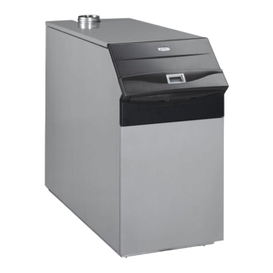
Power HT
Floor standing condensing gas boilers
AUS
EN
AUS
EN
0085
0085
Installation, operation and maintenance Manual
Floor standing condensing gas boilers
Installation, operation and maintenance Manual
Hydroheat Supplies Pty Ltd
PO Box 1045, 6 Helen Kob Drive
Braeside VIC 3195
Ph 03 9588 1299 Fax 03 9588 2199
Hydroheat Supplies Pty Ltd
PO Box 1045, 6 Helen Kob Drive
Braeside VIC 3195
Ph 03 9588 1299 Fax 03 9588 2199
HydroHeat Supplies Pty. Ltd.
6 Helen Kob Drive, Braeside, Victoria 3195
Phone: (03) 9588 1299 Fax: (03) 9588 2199
Web: hydroheat.com.au
Advertisement
Table of Contents

Related Manuals for Baxi HT 1.850


Summary of Contents for Baxi HT 1.850
- Page 1 Power HT Floor standing condensing gas boilers Installation, operation and maintenance Manual Hydroheat Supplies Pty Ltd Floor standing condensing gas boilers PO Box 1045, 6 Helen Kob Drive Braeside VIC 3195 Installation, operation and maintenance Manual Ph 03 9588 1299 Fax 03 9588 2199 Hydroheat Supplies Pty Ltd PO Box 1045, 6 Helen Kob Drive Braeside VIC 3195...
- Page 2 (ISO 9001), environmental (ISO 14001) and health and safety (OHSAS 18001) systems. This means that BAXI S.p.A. includes among its objectives the safeguard of the environment, the reliability and quality of its products, and the health and safety of its employees.
-
Page 3: Table Of Contents
CONTENTS ISTRUCTIONS PERTAINING TO THE USER 1. Instructions prior to installation 2. Instructions prior to commissioning 3. Commissioning of the boiler 4. Filling the boiler 5. Switching the boiler off 6. Prolonged standstill of the system. Frost protection 7. Servicing instructions and gas change ISTRUCTIONS PERTAINING TO THE INSTALLER 8. -
Page 4: Istructions Pertaining To The User
1. INSTRUCTIONS PRIOR TO INSTALLATION This appliance shall be installed in accordance with the manufacturer’s installation instructions, local gas t- ting, electrical and water authority regulations, municipal building codes, AS5601 - Gas Installations and any other relevant statutory regulations. This boiler is designed to heat water at a lower than boiling temperature at atmospheric pressure. -
Page 5: Commissioning Of The Boiler
3. COMMISSIONING OF THE BOILER To correctly light the burner proceed as follows: 1) provide power supply to the boiler; 2) open the gas cock; 3) follow the directions given below regarding the adjustments to be made at the boiler control panel. Figure 1 IMPORTANT: Domestic Hot Water (D.H.W.) instructions here discribed, are to take in account only if the boiler is connected to a D.H.W. - Page 6 3.1 DESCRIPTION OF KEYS (2) Central heating water temperature setting key. This key can be pressed to set the central heating water output temperature as described in point 3-3. (3) Domestic hot water temperature setting key. This key can be pressed to set the domestic hot water temperature as described in point 3-4.
- Page 7 3.2 SETTING THE TIME • Press either of the keys to access the programming function; the display will show the letter P followed by a number (program line); Figure 3 • press the keys until the display shows P1, referring to the time to be set; •...
- Page 8 3.5 SETTING THE DAILY PROGRAM FOR OPERATION IN CENTRAL HEATING AND DOMESTIC HOT WATER MODES 3.5.1 Setting the daily times for central heating mode operation - Press either of the keys to access the programming function; a) press these keys until the display shows P11, referring to the program start time; b) press the keys to set the time;...
- Page 9 3.7 TABLE FO USER-SETTABLE PARAMETERS Parameter Factory Parameter description Range setting Time of day setting ———- 0…23:59 Minimum central heating temperature setting (°C) 25..80 Start of rst daily period of automatic central heating 6:00 00:00…24:00 End of rst daily period of automatic central heating 22:00 00:00…24:00 Start of second daily period of automatic central heating...
- Page 10 3.9 TABLE OF FAULTS AND ERROR MESSAGES Error code Description of fault Corrective action Outdoor temperature sensor fault call the authorised service centre. NTC output sensor failure call the authorised service centre NTC return heating probe faulty call the authorised service centre domestic hot water ntc sensor failure call the authorised service centre Safety or fumes thermostat or heating return...
-
Page 11: Filling The Boiler
Lastly, vent any radiators in the system. BAXI declines all liability for damage deriving from the presence of air bubbles in the primary exchanger due to the incorrect or imprecise observance of the above. -
Page 12: Istructions Pertaining To The Installer
8. GENERAL INFORMATION The following remarks and instructions are addressed to Service Engineers to help them carry out a faultless installation. Instructions regarding lighting and operation of the boiler are contained in the ‘Instructions per- taining to the user’ section. Note that installation, maintenance and operation of the gas appliances must be performed exclusively by quali ed personnel in compliance with current standards. -
Page 13: Boiler Installation And Dimensions
Lastly, vent any radiators in the system. BAXI declines all liability for damage deriving from the presence of air bubbles in the primary exchanger due to the incorrect or imprecise observance of the above. - Page 14 Depth Fitting Fitting Model Height Wight Water contents (mm) POWER (mm) (mm) fitting ( l ) HT.. (CH) (CH) 1.850 ” G 1’’ G 1’’ 13,7 1.1000 G 1” ” ” 1.1200 1024 G 1” ” ” 23,3 1.1500 1132 G 1”...
- Page 15 For the choice of water sepa- rator refer to the declaration made by the manufacturer, according to the water flow rates given in the table below CONDENSATE DRAIN Figure 6 10.1 BOILER PRESSURE LOSS Minimum water Water flow rate POWER HT flow rate with ∆t=20°K Model...
- Page 16 POWER HT 1.850 - 1.1000 EXCHANGERS PRESSURE DROP. WATER FLOW RATE (l/h) Graph 1 120 kW POWER HT 1.1200 - 1.1500 EXCHANGERS PRESSURE DROP. WATER FLOW RATE (l/h) Graph 1.1 ISTRUCTIONS PERTAINING TO THE INSTALLER 910.026.1 - EN (AUS) hydroheat.com.au...
-
Page 17: Chimney Ue Connection
Figure 7 In case exhaust and intake flues not supplied by BAXI S.p.A. have been installed, these must be certified for the type of use and must have a maximum pressure drop in according to the values reported in the table. - Page 18 P available with single P available with ue duct B23 Ø 100 Clapet Ø 110/110 double Clapet Ø 110/110 HT 1.850 HT 1.1000 HT 1.1200 HT 1.1500 WARNING To guarantee more operating insurance it is necessary to assure the flue pipes to the wall using the apposite clamps 11.2 CONNECTOR WITH C53 TYPE...
-
Page 19: Connecting The Mains Supply
12. MAKING THE ELECTRICAL CONNECTIONS Electrical safety of the appliance is only guaranteed by correct grounding, in accordance with the rules in force. Connect the boiler to a 230V monophase + ground power supply by means of the three-pin cable supplied with it and make sure you connect polarities correctly. - Page 20 12.2 CONNECTING THE PUMPS The pumps of the heating system (P1 and P2) have to be connected to boiler terminal block following the wir- ing of gure 9, a relay must be wired between the boiler control circuit board and the pumps. Cover Terminal board Terminal board...
- Page 21 12.4 CONNECTING THE QAA73 TEMPERATURE REGULATOR The SIEMENS model QAA73 temperature regulator (optional accessory) must be connected to terminals 1-2 of terminal block M2 in gure 8. The jumper across terminals 3-4, provided for connection of a room temperature thermostat, must be removed. The settings of the domestic hot water temperature and domestic hot water production schedule must be made using this device.
- Page 22 12.5 CONNECTING THE OUTDOOR TEMPERATURE SENSOR PROBE The SIEMENS model QAC34 outdoor temperature sensor probe (optional accessory) must be connected to terminals 7-8 of terminal board M2 in gure 8. The procedures for setting the gradient of the temperature curve “kt” vary depending on the accessories connected to the boiler.
- Page 23 c) with AGU2.500 for control of a low temperature system: Refer to the instructions provided with the AGU2.500 accessories for connection and control of a low tem- perature zone. In this case some electronic parameters must be modi ed (see §14) (H552-H553-H632). 12.6 CONNECTING A ZONE SYSTEM The electrical connection and settings needed to control a system divided into zones vary depending on the accessories connected to the boiler.
- Page 24 12.7 DOMESTIC HOT WATER CIRCUIT ELECTRIC PUMP CONNECTIONS Fit the hot water tank after the hydraulic header. Connect the pump of the external DHW boiler to terminals 13-14 on terminal block M3 ( gure 9). Make sure that the pump has the following speci cations: 230 V AC;...
-
Page 25: Adjusting The Gas Valves And Gas Change
13. ADJUSTING THE GAS VALVES POWER HT models 1. 850 and 1.1000 have a single gas valve ( gure 12 a). POWER HT models 1. 1200 and 1.1500 have a double gas valve ( gure 12 b). gas nozzle Figure 12a gas nozzle gas manifold LEGEND:... - Page 26 13.1 SINGLE GAS VALVE MODELS (POWER HT 1.850 AND 1.1000) FIGURE 12a Proceed as follows to adjust the single gas valve: • Insert the fume analysis probe into the fume sampling hole as instructed in section 17 ( gure 15).
- Page 27 Turn the screw anti-clockwise to decrease pressure (CO decreasing). • Remove the pressure gauge from the P1OUT port and connect to the P2OUT port of gas valve 2. • Turn the adjuster screw K2 of gas valve 2 so as to set the pressure value (Pout) as indicated in table 2.1 for natural gas (G20) and in table 2.2 for propane (LPG): •...
- Page 28 Gas consumption at 15 °C POWER HT POWER HT POWER HT POWER HT Natural Gas - 1.13 kPa 1.850 1.1000 1.1200 1.1500 MJ/m 34,02 34,02 34,02 34,02 Consumption at max. heat output 9,26 10,9 13,08 16,35 Consumption at min. heat output 3,50 3,89 4,23...
-
Page 29: Setting The Boiler Parameters
14. SETTING THE BOILER PARAMETERS The boiler parameters may only be modi ed by professionally quali ed staff proceeding as follows: a) press the , keys on the boiler’s front panel together for about 3 s until the parameter H90 appears on the display;... -
Page 30: Control And Operation Devices
15. CONTROL AND OPERATION DEVICES The boiler has been designed in full compliance with European reference standards and in particular is equipped with the following: • Overheat safety thermostat Thanks to a sensor placed on the heating ow, this thermostat interrupts the gas ow to the main burner in case the water contained in the circuit has overheated. -
Page 31: Positioning Of The Ignition And Ame Sensing Electrode
16. POSITIONING OF THE IGNITION AND FLAME SENSING ELECTRODE Figure 14 17. CHECK OF COMBUSTION PARAMETERS Drill a hole in the ue at a distance from the boiler equivalent to twice the diameter of the ue to measure combustion ef ciency and combustion ue composition in accordance with the rules in force. Use this hole to measure the following parameters: •... -
Page 32: Activating The Ue-Sweeper Function
18. ACTIVATING THE CHIMNEY SWEEP FUNCTION To facilitate measurement of the combustion ef ciency and improve the cleanliness of the production products, the chimney sweep function can be activated by proceeding as described below: 1) press the (2-3) together until the pointer “ ” appears on the display alongside the symbol (about 3 seconds but no more than 6 seconds). -
Page 33: Boiler Schematic
20. BOILER SCHEMATIC Figure 17 Key: 11 gas diaphragm 1 pressure gauge 12 fan 2 siphon 13 flue joint 3 NTC delivery heating probe 14 automatic air vent 4 105°C overheat safety thermostat 15 hydraulic pressure sensor 5 gas valve 16 boiler drain point 6 flue-water exchanger 17 joint flue with flue thermostat... -
Page 34: Illustrated Wiring Diagram
21. ILLUSTRATED WIRING DIAGRAM 21.1 POWER HT 1.850 - 1.1000 910.026.1 - EN (AUS) ISTRUCTIONS PERTAINING TO THE INSTALLER hydroheat.com.au... - Page 35 21.2 POWER HT 1.1200 - 1.1500 ISTRUCTIONS PERTAINING TO THE INSTALLER 910.026.1 - EN (AUS) hydroheat.com.au...
-
Page 36: Technical Data
*C53 (only with air intake kit) BAXI S.p.A., in its commitment to constantly improve its products, reserves the right to alter the speci cations contained herein at any time and without previous warning. These Instructions are only meant to provide consumers with use information and under no circumstance should they be construed as a contract with a third party.
Need help?
Do you have a question about the HT 1.850 and is the answer not in the manual?
Questions and answers