Table of Contents
Advertisement
Quick Links
Advertisement
Table of Contents

Related Manuals for Elcometer 1535


Summary of Contents for Elcometer 1535
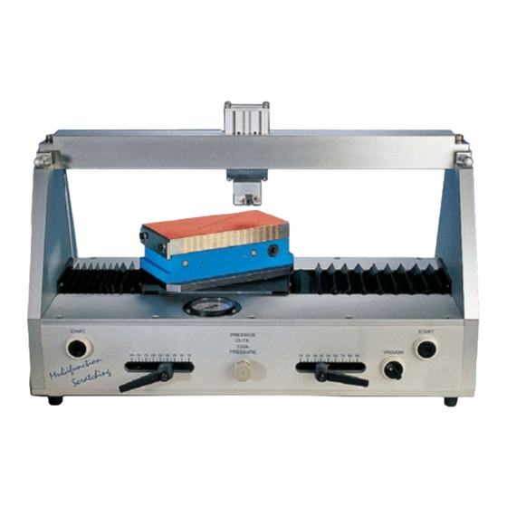
- Page 1 Elcometer 1535 Multi Function Scratch Tester Operating Instructions...
- Page 2 Elcometer Instruments Ltd. All other trademarks acknowledged. © Copyright Elcometer Instruments Ltd. 2007. All rights reserved. No part of this Document may be reproduced, transmitted, transcribed, stored (in a retrieval system or otherwise) or translated into any...
-
Page 3: Table Of Contents
CONTENTS Section Page About your tester ......... 2 1.1 Standards . -
Page 4: About Your Tester
Our products cover all aspects of coating inspection, from development through application to post application inspection. The Elcometer 1535 Multi Function Scratch Tester, is a world beating product. With the purchase of this product you now have access to the worldwide service and support network of Elcometer. -
Page 5: Standards
1.1 Standards Your Elcometer 1535 Multi Function Scratch Tester can be used in accordance with the following national and international standards: • ASTM D 3359 • DIN EN ISO NF 2409 • DIN 53167 • DIN 53799 • ISO 4586 1.2 What the box contains... -
Page 6: Getting Started
2 GETTING STARTED This section of the instructions is intended for first-time users of the Elcometer 1535 Multi Function Scratch Tester. It contains information on the parts and controls of the instrument, connecting to services and advice on safe use of the equipment. -
Page 7: Connecting To A Compressed Air Supply
2.2 Connecting to a compressed air supply 1. Connect the filter supplied with your tester to a compressed air supply; installation of a stopcock before the filter is recommended. Figure 2. Compressed air filter connected to inlet at rear of tester 2. -
Page 8: Caution
It is always advisable to start at low tool pressure and gradually increase pressure until good results are obtained. If you are unable to obtain satisfactory results, please contact Elcometer or your local supplier for technical advice. -
Page 9: Tungsten Carbide Din Tool
3.2 Tungsten carbide DIN tool Your Elcometer 1535 Multi Function Scratch Tester is supplied with a DIN 1 mm scratching tool as standard equipment (part number KT001538N001). The tool holder is also supplied as standard equipment. Tool Part number DIN tool... -
Page 10: Other Tools
0.8 / 12 (Tungsten carbide) KT003092P002 0.75 2 / 30 KT003092P003 1 4 / 60 Coin scratch disc (Hardened steel) KT001538N008 To order any of these scratching tools for your Elcometer 1535, see “Spare parts and accessories” on page 22. -
Page 11: Removing And Fitting A Scratching Tool
3.4 Removing and fitting a scratching tool Before removing or fitting a scratching tool, always move the table out of the way - see steps 1 and 3. This will prevent damage to the surface of the table in the event that a tool or the tool holder is dropped accidentally. - Page 12 8. Loosen the two pneumatic cylinder height adjustment levers (Figure 6). 9. Adjust the height of the pneumatic cylinder until the gap between the specimen and the bottom of the tool is approximately 3 mm (Figure 6). 10.After adjustment, tighten the two levers. 3 mm Figure 6.
-
Page 13: Checking And Adjusting The Angle Of The Tool Holder
3.5 Checking and adjusting the angle of the tool holder When creating scratches using the optional cross cut tools (see “Spare parts and accessories” on page 22), it is essential that the angle of the tool is adjusted until the cutting edge of the tool is parallel to the surface of the specimen. 3.5.1 Checking the angle of the tool holder To check that the angle of the tool is correct: 1. - Page 14 3.5.2 Adjusting the angle of the tool holder To adjust the angle of the tool: 1. Loosen the securing bolt on each end of the cross bar at the top of your tester. 2. Rotate the two micrometers towards (A) or away from (B) zero by the same amount.
-
Page 15: Mounting A Specimen
4 MOUNTING A SPECIMEN Specimens are placed on the table and held flat against the table by the action of magnetism (for ferrous specimens) or vacuum (optional feature for non-ferrous specimens). The ideal specimen size is 200 mm x 100 mm (8" x 4"). - Page 16 2. Place the specimen onto the table in contact with the two stop blocks if necessary (Figure 8). Figure 8. Mounting specimen on magnetic table 3. Insert the wrench supplied with your tester and rotate clockwise to switch on the magnet and secure the specimen (Figure 9). Always remove the wrench before pressing the start buttons.
-
Page 17: Non-Ferrous Specimens (Using Optional Vacuum Table)
4.2 Non-ferrous specimens (using vacuum table version) 1. Ensure that the rubber vacuum sealing ring is clean and is securely fitted into the groove. Place the specimen onto the vacuum table ensuring that the specimen covers the rubber vacuum sealing ring (Figure 10). The edge of the specimen should be no closer than 10 mm from the vacuum sealing ring;... -
Page 18: Setting The Scratch Angle
6. When the scratches have been produced, rotate the vacuum on/off control anticlockwise to release the vacuum and then remove the specimen. 5 SETTING THE SCRATCH ANGLE The table rotates and can be set at angles of -90° , -45° , -30° , 0° , 30° , 45° and 90°... - Page 19 3. Loosen the start and stop position handles, slide them to the required positions and then tighten. Start position Stop position adjustment adjustment Figure 12. Setting scratch length...
-
Page 20: Testing A Specimen
7 TESTING A SPECIMEN 1. Push the sliding stopcock at the rear of the tester to its closed position. 2. Push the table to the left as far as it will go. 3. Push the sliding stopcock to its open position. See page 5. 4. - Page 21 6. Press and hold both start buttons at the same time to start the scratch (Figure 13). Figure 13. Press and hold to start a scratch The tool cylinder moves down until the tool makes contact with the specimen and then the table moves from its start position to its stop position to produce the scratch.
-
Page 22: Air Pressure/Force
(kg) (bar) 9 MAINTENANCE The Elcometer 1535 Multi Function Scratch Tester is designed to give many years reliable service under normal operating and storage conditions. The table must be kept clean and free from knocks. Ensure supply is disconnected and ventilated to the atmosphere during cleaning. Any deformation of the surface of the table will adversely affect the quality of the scratches, especially cross cut scratches. -
Page 23: Technical Specification
Details of Elcometer offices around the world are given on the outside cover of these Operating Instructions. Alternatively visit the Elcometer website, www.elcometer.com 10 TECHNICAL SPECIFICATION Table dimensions: 200 mm x 100 mm (7.9" x 3.9") Stroke length: 20 mm to 180 mm (0.8"... -
Page 24: Spare Parts And Accessories
11 SPARE PARTS AND ACCESSORIES The Elcometer 1535 Multi Function Scratch Tester is complete with all the items required to get started and take readings. The following spare parts and optional accessories are available from your local supplier or direct from Elcometer:... -
Page 25: Related Equipment
In addition to the Elcometer 1535 Multi Function Scratch Tester, Elcometer produces a wide range of other equipment for determining the physical characteristics of surface coatings. Users of the Elcometer 1535 Multi Function Scratch Tester may also benefit from the following Elcometer products: •...
Need help?
Do you have a question about the 1535 and is the answer not in the manual?
Questions and answers