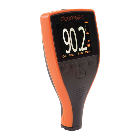
Elcometer 456 Operating Instructions Manual
Miniature probe
Hide thumbs
Also See for 456:
- User manual (112 pages) ,
- Operating instructions manual (67 pages) ,
- Operating instructions manual (16 pages)
Advertisement
Quick Links
Advertisement

Summary of Contents for Elcometer 456
- Page 1 Elcometer 456 Miniature Probe Operating Instructions...
- Page 2 3V/m. Warning The Elcometer 456 gauge uses a Liquid Crystal Display. If it is heated above 50° C (120° F) it may be damaged. This can happen if it left in a car parked in strong sunlight.
-
Page 3: Table Of Contents
CONTENTS Section Page Introduction ..............2 Operating Instruction . -
Page 4: Introduction
They can be used on anodising, paint, plastic coatings, powder, etc applied to aluminium, brass, non-magnetic stainless steel, etc. The package for the 456 miniature probe contains the scale 3 miniature probe, FM3 or NM3, and an appropriate set of measured foils. -
Page 5: Operating Instruction
2 OPERATING INSTRUCTION When fitting the FM3 miniature probe to the Elcometer 456 gauge ensure that the gauge is switched off before the old probe is removed and the new probe fitted. This allows the data stored in the probe to be read... - Page 6 When a new type of probe is fitted to the Elcometer 456 gauge the gauge factory reset feature should be used to set the gauge to the calibration conditions set in the memory of the probe during its final test in the factory.
-
Page 7: Calibration Adjustment
Full details of the calibration adjustment methods available on the Elcometer 456 gauges are given in the Elcometer 456 operating instructions. To activate the calibration adjustment procedure select CAL from the READING SCREEN. The gauge will show full instructions with graphical and text support. -
Page 8: Technical Specification
0.1 mil from 4 - 10 mil is the greater Measured with the probe held in a placement jig, using measured foils and the Elcometer zero plate. 1% accuracy is achieved when calibrating close to the coating thickness value to be measured. - Page 9 Probe Type Part Number Minimum Convex Minimum Concave Diameter Radius FERROUS MINIATURE Ferrous Straight 45mm Long T456FM3---A 1.5mm (0.06”) 6.5mm (0.26”) Ferrous Straight, 150mm Long T456FM3---C 1.5mm (0.06”) 6.5mm (0.26”) Ferrous 45 Degree, 45mm Long T456FM3R45A 1.5mm (0.06”) 6.5mm (0.26”) Ferrous 45 Degree, 150mm Long T456FM3R45C 1.5mm (0.06”)
- Page 10 Probe Type Minimum Minimum Access Requirements Overall Length Sample (Headroom) Diameter FERROUS MINIATURE Height Width Ferrous Straight 45mm Long 3mm (0.12”) 6mm (0.24”)* 150mm (5.91”) Ferrous Straight, 150mm Long 3mm (0.12”) 6mm (0.24”)* 260mm (10.24”) Ferrous 45 Degree, 45mm Long 3mm (0.12”) 18mm (0.71”) 7mm (0.28”)
-
Page 11: Probe Alignment Jig
5 PROBE ALIGNMENT JIG To aid probe positioning on small components a Probe Placement Jig is available and an adapter suitable for use with the full range of miniature probes is also available as an accessory. T95012880 Probe Placement Jig T95016896 Universal Jig Adapter for All Miniature Probes (optional) includes a Special Probe Jig Adapter for Miniature Straight 45mm... - Page 12 Figure 1. Probe Jig Adapter for Miniature Straight 45mm Probes...
- Page 13 5.2 USE OF THE UNIVERSAL JIG ADAPTER The Universal Jig Adapter accommodates all the different options of the Miniature probes. The assembly of the adapter on to the Probe Placement Jig is shown in Figure 2. Probes held in the Universal Jig Adapter do not have any spring loading and should therefore be placed carefully on any coated surface to ensure that the surface does not become indented.
- Page 14 The Universal Jig Adapter has two faces to allow the fitting of the different miniature probe options as shown in Figure 3. FACE ‘B’ FACE ‘A’ Figure 3. Detail of the Adapter Showing the two Faces The probes can be fitted in to the Universal Jig Adapter as shown in Figure 4.
- Page 15 FACE ‘A’ Figure 4a. Fitting of the Miniature Probe in to the Universal Jig Adaptor - Straight Probes.
- Page 16 FACE ‘A’ Figure 4b. Fitting of the Miniature Probes in to the Universal Jig Adapter - 45° Probes...
- Page 17 FACE ‘B’ Figure 4c Fitting of the Miniature Probes in to the Universal Jig Adapter - 90° Probes...
-
Page 18: Servicing
In the unlikely event of a fault that cannot be corrected using the information contained in this operating instruction or the operating instruction for the Elcometer 456, the miniature probe and the gauge should be returned to your local Elcometer Dealer or directly to Elcometer Ltd.


Need help?
Do you have a question about the 456 and is the answer not in the manual?
Questions and answers