Advertisement
Quick Links
Advertisement

Subscribe to Our Youtube Channel
Related Manuals for Elcometer 1615


Summary of Contents for Elcometer 1615
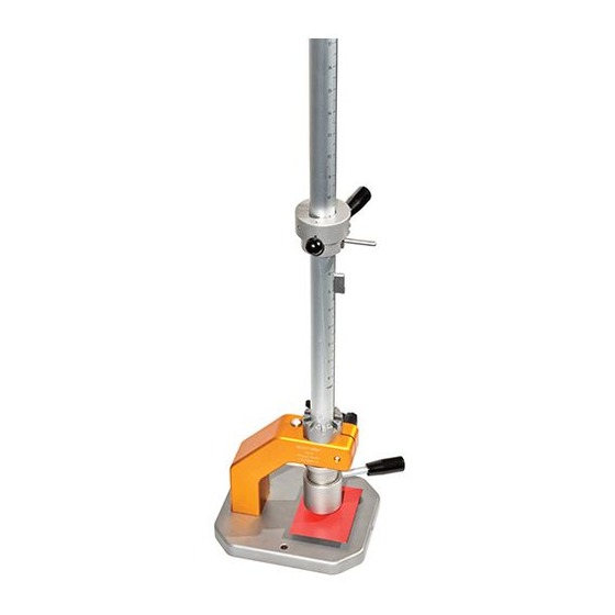
- Page 1 Elcometer 1615 Variable Impact Tester - Kit of Parts - Operating Instructions...
- Page 2 (electronic, mechanical, magnetic, optical, manual or otherwise) without the prior written permission of Elcometer Limited. A copy of this Instruction Manual is available for download on our Website via www.elcometer.com/ downloads. Doc.No. TMA-0439 Issue 02...
-
Page 3: Table Of Contents
CONTENTS Section Page About this kit of parts ............. 2 Adjusting the guide tube of the basic tester . -
Page 4: About This Kit Of Parts
Your Elcometer 1615 Variable Impact Tester is a world beating product. With the purchase of this kit of parts you now have access to the worldwide service and support network of Elcometer. For more information visit our website at www.elcometer.com... - Page 5 1.1 WHAT THE BOX CONTAINS For testing to standard Box contents ISO 6272:1993 • Falling indenter with handle, stop key and a punch (20 EN 13523-5:2001 mm) (total mass = 1 kg). JIS K 5600-5-3:1999 • Die (27 mm) with fixing screw DIN EN ISO 6272-1:2004 •...
- Page 6 For testing to standard Box contents ISO 6272-1:2002 • Falling indenter with handle, stop key and punch (20 BS EN ISO 6272-1:2004 mm) (total mass = 1 kg). • Die (27 mm) with fixing screw • Specimen clamp with two fixing screws •...
- Page 7 For testing to standard Box contents ISO 6272:1993 • Falling indenter with handle, stop key and a punch (20 EN 13523-5:2001 mm) (total mass = 1 kg). JIS K 5600-5-3:1999 • Weight with handle (1 kg) DIN EN ISO 6272-1:2004 •...
-
Page 8: Adjusting The Guide Tube Of The Basic Tester
2 ADJUSTING THE GUIDE TUBE OF THE BASIC TESTER 1. Raise the indenter by lifting the handle. 2. Place the specimen on the die and clamp in place by rotating the specimen clamp (if fitted to your tester). 3. Lower the indenter gently until the punch rests on the specimen. 4. -
Page 9: Fitting The Parts Onto The Basic Tester
3 FITTING THE PARTS ONTO THE BASIC TESTER Note: Your test kit may not include all the parts listed below. 1. Die Place die (1) into hole in base plate and fix in place using the screw provided in the kit of parts (1a). 2. -
Page 10: Assembling The Kits
4. Release collar Slide release collar (4) onto guide tube and then tighten fixing screw (4a). Note: Fit this item after inserting the indenter and any weights required. 4 ASSEMBLING THE KITS Before assembling any of the test kits, first check that the guide tube is positioned correctly in the guide tube supporting arm clamp and adjust if necessary - see “Adjusting the guide tube of the basic tester”... - Page 11 4.1 ASSEMBLING KIT A 1. Fit die into base. 2. Fit specimen clamp onto base. 3. Fit stop collar onto base. 4. If required, add additional weight(s) to indenter and tighten fixing screw(s). 5. Slide indenter down inside guide tube until it reaches the bottom of the tube.
- Page 12 4.2 ASSEMBLING KIT B 1. Fit die into base. 2. Slide indenter down inside guide tube until it reaches the bottom of the tube. 3. Slide weight down inside guide tube until it rests on the top of the indenter. 4.
- Page 13 Kit B is supplied with the 15.9 mm punch already fitted to the indenter and the 12.7 mm punch loose for the user to fit as required. To fit the punch, insert the punch (1) into the hole in the end of the indenter and fix in place using the screw (1a) provided with the kit.
- Page 14 4.5 ASSEMBLING KIT E 1. Fit die into base. 2. Slide indenter down inside guide tube until it reaches the bottom of the tube. 3. Fit release collar onto guide tube.
-
Page 15: Spares And Accessories
Falling weight + static indenter/punch Use 16.3mm die (Kit B) (15.9mm or 12.7mm) 5 SPARES AND ACCESSORIES The following spare parts and optional accessories are available from your local supplier or direct from Elcometer: Kit A • Kit A complete KT001615KITA •... - Page 16 Kit B • Kit B complete KT001615KITB • Punch (12.7 mm) KT001615N215 • Punch (15.9 mm) KT001615N205 • Die (16.3 mm) with fixing screw and hexagonal wrench KT001615N212 Kit C • Kit C complete KT001615KITC • Punch (15.9 mm) KT001615N205 •...
- Page 17 Kit E • Kit E complete KT001615KITE • Punch (23 mm) KT001615N207 • Die (22 mm) with fixing screw and hexagonal wrench KT001615N213 Kit F • Kit A complete plus Kit B complete KT001615KITF • Punch (20 mm), Outside Diameter: 25mm KT001615N226 •...
-
Page 18: Related Equipment
6 RELATED EQUIPMENT In addition to the Elcometer 1615 Variable Impact Tester, Elcometer produces a wide range of other equipment for determining the physical characteristics of surface coatings. Users of the Elcometer 1615 Variable Impact Tester may also benefit from the following Elcometer products: •...
Need help?
Do you have a question about the 1615 and is the answer not in the manual?
Questions and answers