Table of Contents
Advertisement
Quick Links
Chipsmall Limited consists of a professional team with an average of over 10 year of expertise in the distribution
of electronic components. Based in Hongkong, we have already established firm and mutual-benefit business
relationships with customers from,Europe,America and south Asia,supplying obsolete and hard-to-find components
to meet their specific needs.
With the principle of "Quality Parts,Customers Priority,Honest Operation,and Considerate Service",our business
mainly focus on the distribution of electronic components. Line cards we deal with include
Microchip,ALPS,ROHM,Xilinx,Pulse,ON,Everlight and Freescale. Main products comprise
IC,Modules,Potentiometer,IC Socket,Relay,Connector.Our parts cover such applications as commercial,industrial,
and automotives areas.
We are looking forward to setting up business relationship with you and hope to provide you with the best service
and solution. Let us make a better world for our industry!
Contact us
Tel: +86-755-8981 8866 Fax: +86-755-8427 6832
Email & Skype: info@chipsmall.com Web: www.chipsmall.com
Address: A1208, Overseas Decoration Building, #122 Zhenhua RD., Futian, Shenzhen, China
Advertisement
Table of Contents

Related Manuals for red lion PCU


Summary of Contents for red lion PCU
- Page 1 Chipsmall Limited consists of a professional team with an average of over 10 year of expertise in the distribution of electronic components. Based in Hongkong, we have already established firm and mutual-benefit business relationships with customers from,Europe,America and south Asia,supplying obsolete and hard-to-find components to meet their specific needs.
- Page 2 THE PROCESS CONTROL UNIT MODEL PCU INSTRUCTION MANUAL...
- Page 3 The PCU unit, which you have purchased, has the same high quality workmanship and advanced technological capabilities that have made Red Lion Controls the leader in today’s industrial market.
-
Page 4: Table Of Contents
Table of Contents GENERAL DESCRIPTION ..............1 Safety Summary . - Page 5 Configuration Of Parameters ..............14 Parameter Entry .
- Page 6 Input Overdrive Preset Power (OPFL) ........... . . 25 Output Power Dampening (OPdP) .
- Page 7 Decimal Point Position (dPt2) ............36 Second Analog Input Scaling Points (dSP1, INP1, dSP2, INP2) .
- Page 8 Terminal Descriptions ..............52 Connecting To A Host Terminal .
- Page 9 Output Leakage Current ..............75 APPENDIX “D”...
-
Page 10: General Description
GENERAL DESCRIPTION The PCU Controller accepts either a 0 to 10 VDC or a 4 to 20 mA DC input The optional Motorized Valve Positioner directly controls the position of a signal, precisely scales the process signal according to programmable scaling... -
Page 11: Safety Summary
Do not use the PCU to directly command motors, valves, or other actuators industrial environments. not equipped with safeguards. To do so, can be potentially harmful to persons or equipment in the event of a fault to the unit. -
Page 12: Installation & Connections
NEMA 4X/IP65 UNIT INSTALLATION INSTALLATION ENVIRONMENT The optional NEMA 4X/IP65 PCU Controller provides a watertight seal in panels with a minimum thickness of 1/8 inch. The units meet NEMA 4X/IP65 The unit should be installed in a location that does not exceed the maximum requirements for indoor use, when properly installed. -
Page 14: Unit Removal Procedure
UNIT REMOVAL PROCEDURE To remove a NEMA 4X/IP65 or standard unit from the panel, first unscrew and remove the panel latch screws. Insert flat blade screwdrivers between the latch and the case on the top and bottom of the unit, so that the latches disengage from the grooves in the case. -
Page 15: Installing Output Modules
Installing Output Modules To install an output module into the controller, remove the bezel assembly from the case (See Removing Bezel Assembly, page 5). Locate the correct output module socket (OP1, AL1, or AL2/OP2, see Figure 6, Hardware, or label outside of case) and plug the output module into the socket. No re-programming is required. -
Page 16: Emc Installation Guidelines
EMC INSTALLATION GUIDELINES Although this unit is designed with a high degree of immunity to ElectroMagnetic Interference (EMI), proper installation and wiring methods must be followed to ensure compatibility in each application. The type of electrical noise, source or coupling method into the unit may be different for various installations. -
Page 17: Wiring Connections
to suppress power line interference. Install them near the power entry point of the enclosure. The following EMI suppression devices (or equivalent) are recommended: Ferrite Suppression Cores for signal and control cables: Fair-Rite # 0443167251 (RLC #FCOR0000) TDK # ZCAT3035-1330A Steward #28B2029-0A0 Line Filters for input power cables: Schaffner # FN610-1/07 (RLC #LFIL0000) -
Page 18: Valve Positioner Wiring
In some cases, it may be desirable to have an independent valve position indicator. Red Lion Controls Model IMD1 can be wired in parallel with the slidewire input’s Wiper and Comm. terminals for this purpose. The approximate 0 to 0.9V signal can be scaled to indicate percent valve position. -
Page 19: Program Disable Or User Input Wiring
AC Power Wiring Program Disable Or User Input Wiring Primary AC power is connected to the separate two position terminal block Some models have Terminal #7 as the User Input, which is programmable labeled AC. To reduce the chance of noise spikes entering the AC line and for a variety of functions. -
Page 20: Front Panel Description
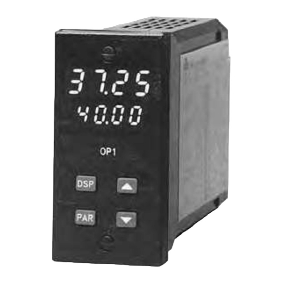
FRONT PANEL DESCRIPTION The front panel bezel material is flame and scratch resistant, tinted plastic. An optional NEMA 4X/IP65 bezel version is available that meets NEMA 4X/IP65 requirements, when properly installed. There are two 4-digit LED displays, a red upper Main Display and a lower green Secondary Display. -
Page 21: Operation Overview
OPERATION OVERVIEW CONTROLLER POWER-UP If the controller is a replacement, the PID settings from the unit being Upon applying power, the controller delays control action and process replaced may be used as good initial values. Be sure to consider any indication for five seconds to perform several self-diagnostic tests and differences in the units and the PID settings when replacing. -
Page 22: Remote And Local Setpoint Operation
REMOTE AND LOCAL SETPOINT OPERATION The controller setpoint mode can be switched between Local Setpoint operation and Remote Setpoint operation. In the Hidden Function Mode, the “SPSL” parameter allows the operator to select the desired setpoint operating mode. To allow front panel switching between setpoint modes, program the setpoint select parameter (SPSL) to “Enbl”... - Page 23 CONFIGURATION OF PARAMETERS Operation and configuration of the controller is divided into five distinct operational/programming modes to simplify the operation of the controller: As supplied from the factory, the controller parameters have been Normal Display Mode, Unprotected Parameter Mode, Protected Parameter programmed to the values listed in the Programming Quick Reference Mode, Hidden Function Mode, and Configuration Parameter Modules.
- Page 24 PARAMETER ENTRY NORMAL DISPLAY MODE The PAR button is used to select the desired parameter. To modify the In the normal display mode, the process value is always displayed in the parameter setting, use the UP and DOWN buttons. Press PAR to enter the new main display.
- Page 25 UNPROTECTED PARAMETER MODE UNPROTECTED PARAMETER MODE REFERENCE TABLE The Unprotected Parameter Mode is accessed by pressing the PAR button from the normal display mode with program disable inactive. In this mode, Range and Description/ the operator has access to the list of the most commonly modified controller Display Parameter Units (Factory...
- Page 26 Range and Description/ Display Parameter Units (Factory Comments Setting Value) dt-2 Derivative 0 to 9999 sec 0 is off. This parameter does not Time #2 appear if proportional band #2 = 0.0%. (Secondary) Second Analog Input models only. SP-2 Internal -999 to 9999 Second Analog Input models only.
Need help?
Do you have a question about the PCU and is the answer not in the manual?
Questions and answers