Table of Contents
Advertisement
Quick Links
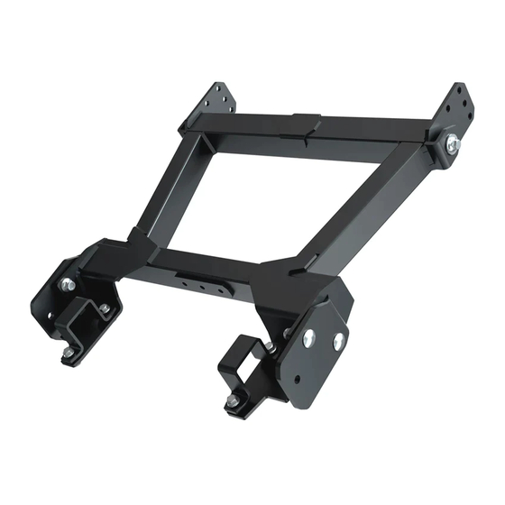
UTV CONQUEROR FRONT-CONNECT
TRACKED VEHICLE PLOW EXTENSION
P/N 35-0350
OWNER'S MANUAL
Application
UTV CONQUEROR FRONT-CONNECT PLOW FRAME NO. 35-0070
ATTENTION DEALER: CUSTOMER MUST RECEIVE A COPY OF THIS MANUAL
AT THE TIME OF SALE.
Before you begin, please read these instructions and check to be sure all parts and tools are
accounted for. These instructions will help you to become familiar with operation of the plow push
frame. Instructions contain details required to install, service the contents of this kit, for adjustment
and maintenance.
© 2021 Kolpin Outdoors Inc.
REV 00
Advertisement
Table of Contents

Related Manuals for Kolpin Outdoors 35-0350


Summary of Contents for Kolpin Outdoors 35-0350
- Page 1 These instructions will help you to become familiar with operation of the plow push frame. Instructions contain details required to install, service the contents of this kit, for adjustment and maintenance. © 2021 Kolpin Outdoors Inc. REV 00...
- Page 2 To increase traction during plow operation, operators can try: Securing weight to the ATV / UTV for additional tire • downforce, reducing tire air pressure, or installing tire chains. © 2021 Kolpin Outdoors Inc. REV 00...
- Page 3 The winch should be installed on the unit prior to installing this kit. © 2021 Kolpin Outdoors Inc. REV 00...
- Page 4 Hex Flange Locknut, Zinc Plated, M10-1.5 Lock Washer, Zinc Plated, M8 Flat Washer, Zinc Plated, M10 Lock Washer, Zinc Plated, M10 Flat Washer, Zinc Plated, M8 Carriage Screw, Zinc Plated, M10-1.5 x 35mm LG Instruction Manual (not shown) © 2021 Kolpin Outdoors Inc. REV 00...
- Page 5 35-0070 Plow Frame as and screws shown. Keep the items as these will be reinstalled onto the rear of 35-0350 extension frame (item #3). (See illustration 1-2). Note, keep the cotter pin and safety wire lock pins installed with the Connection Latch assembly.
- Page 6 (not shown). Ill. 1-5 Lift Point Bracket from 35-0070 kit M8 Screw from 35-0070 kit M8 Locknut from 35-0070 kit © 2021 Kolpin Outdoors Inc. REV 00...
- Page 7 Most hardware is general in nature and is easily obtained locally. Be sure to replace with minimum metric class 8.8 specification. Kolpin Outdoors, Inc. Telephone: (763)-478-5800 Toll Free: (877)-956-5746 Fax Number: (800)-245-7569 www.kolpin.com Email: customerservice@kolpin.com © 2021 Kolpin Outdoors Inc. REV 00...
Need help?
Do you have a question about the 35-0350 and is the answer not in the manual?
Questions and answers